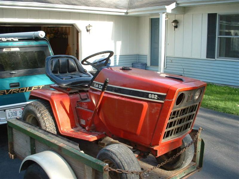
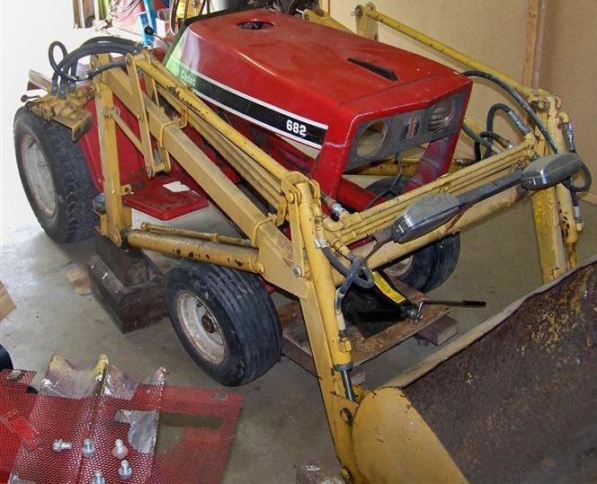
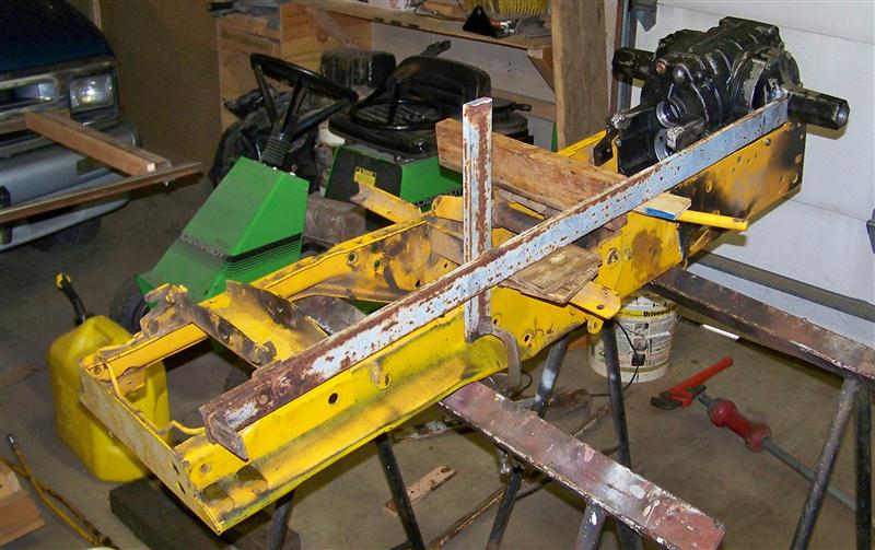
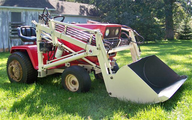
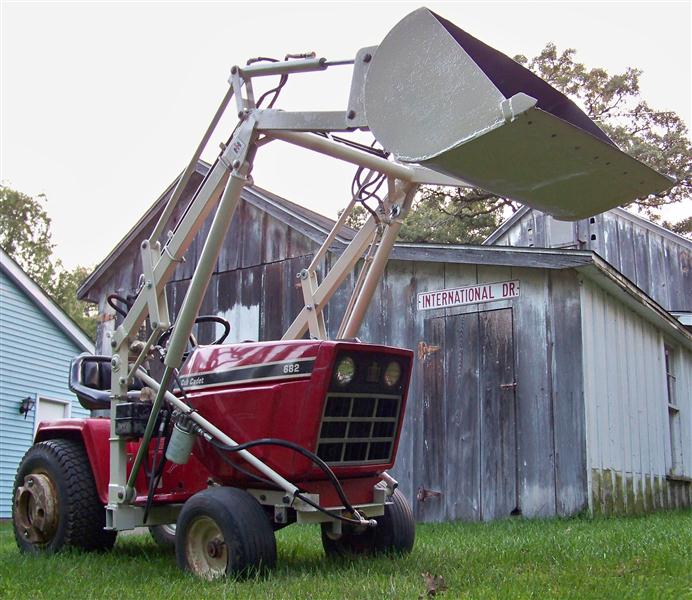
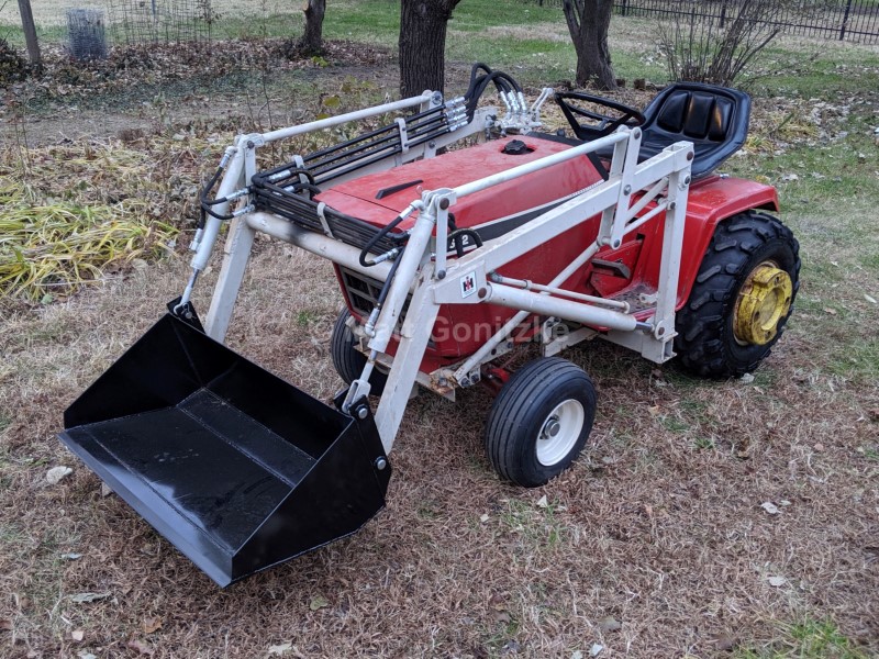
Several years ago, I bought a 124 with a Kwik-Way loader. I decided right away that the gear drive 124 was not the right tractor for the loader. There was no room for the operator's knees, maneuvering the machine was a chore, and the tractor was cobbled and beat up. To me, the ideal loader tractor is about 12 hp and easy to work on. The 82 series tractors are among the easiest to work on. This made the 12 hp 1282 the ideal machine, but finding an affordable one proved nearly impossible. In the spring of 2010, my Dad found an engineless IH-built (October '79) 682 at an auction. A week later, he found a cheap 1250 at another auction. I got the engine in the 1250 running (and found out it was actually a 14 hp engine in the process) and removed it. The 124 was also sold, leaving the loader sitting in a pile in the barn, and ultimately causing me to finish this project over the summer of 2010. Above is the 682 after arriving home from the auction.
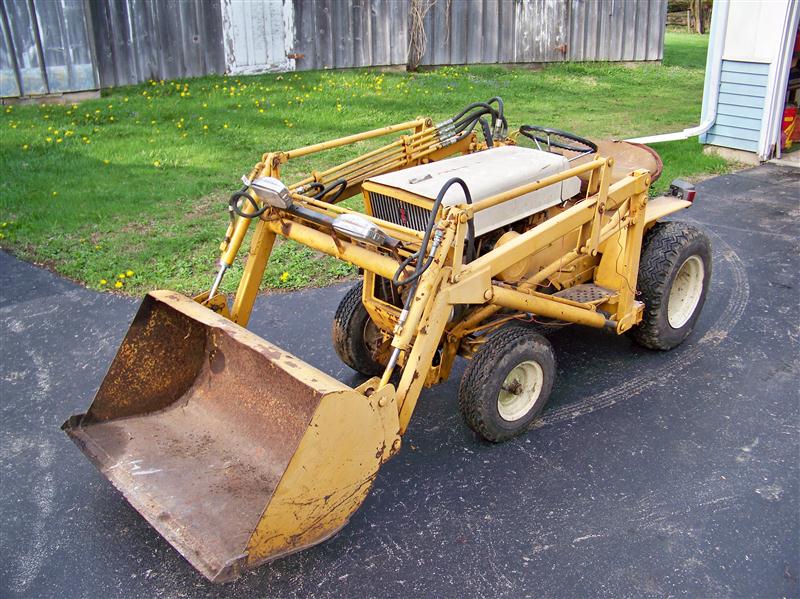
Here's the loader on the 124 as I got it: covered in multiple coats of chalky paint and excessive lights and extra wiring. It was also VERY cobbled. The subframe only attached to the frame, the braces were bent, and there were multiple hydraulic leaks.
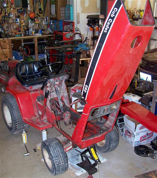
I started by bringing the 682 into the garage and removing what was left of the engine mounting from the KT-17 Series I that used to be in it. It must have leaked oil for quite awhile, as the entire front half of the tractor was a greasy mess. I removed and rebuilt the steering column. It steers MUCH better now, and there is almost no play at all in the steering. I probably should have replaced the original 2-turn column with a 3-turn column from a later tractor to make it steer a bit easier.
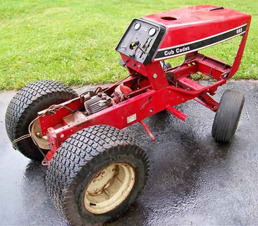
After carefully pressure-washing it, the tractor looks much better. There was quite a bit of dirt on the transaxle, as well. Some say tractors shouldn't be pressure washed because the water can get forced into seals and breathers, but if care is taken around those areas, it isn't a problem.

After some cleaning, I placed the K321AQS (from a 1450) into the tractor to see what would and wouldn't line up right. I used the engine mount rails from the engine's original tractor, but I had to modify them and purchase 'riser' mounts from a 1282 to align the engine with the 682's driveline. This is explained more a bit further down the page.
I reused the 682's wiring, but I had to move most of it to the other side of the tractor, as the start is on the left on a KT-17, but on the right on the K-series singles. I later had to lengthen the starter cable by about 8" to get it to reach. That was the only modification I had to make to the wiring harness; the connector on an AQS K-series and KT-17 are the same.
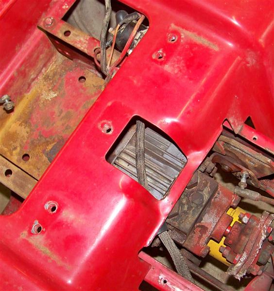
At this time, I put the loader up on blocks and rolled the tractor into it. Several interference issues immediately became obvious. The lift cylinders would hit the front tires if the axle pivoted at all, and putting the bucket all the way down would probably have caused the cylinders to hit the tires, as well. It was also clear that the hydraulic lines would hit the nosepiece of the tractor unless I moved them forward. I moved the lines a bit so I could keep the loader further back on the tractor, giving me a little bit more front tire clearance.
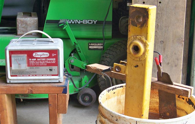
At this point, I wasn't sure if I was going to take everything down to bare metal and repaint. I knew I would need to weld new pieces onto the ends of the uprights, so I cleaned the bottom ends of those in my small electrolysis tank. This is when I really discovered how many coats of horrible paint were covering everything. I later found that the adhesion was horrible, too; most of the paint peeled off easily with a razor blade.
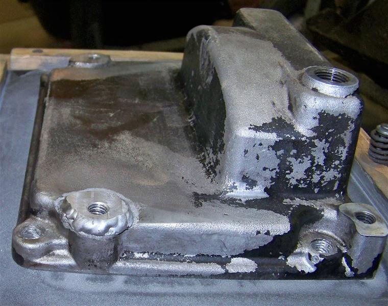
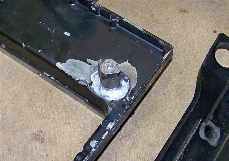
Typical of most QL engines, the oil pan had some serious wear on it as a result of all but one engine mounting bolt vibrating out. The two front pads on the pan were worn down 1/4", and the threads were stripped. Since I didn't particularly want to drop $40+ on a cast-iron oil pan, I had a friend of my Dad's weld up the worn parts, and then I redrilled and retapped the threaded holes. It isn't very pretty, but no one is going to see it.
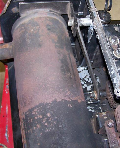
Another common problem with the AQS engines is that the muffler mount post on the aluminum muffler box breaks off from the weight and vibration of the muffler. I also had that welded up, and I braced the muffler to the engine block.
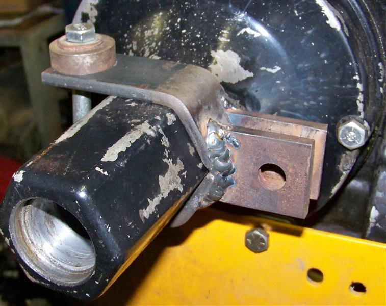
This is the brace I made to lessen the load on the muffler box. It is simply a piece of 1/4" x 1" steel with two bends and two holes. One end connects to the mounting tab on the muffler, and the other connects to the bolt on the engine block where the muffler box connects. This should keep the muffler box from cracking again. I can't take credit for this idea, as it was created by David Kirk, a member of one of the IH Cub Cadet forums.
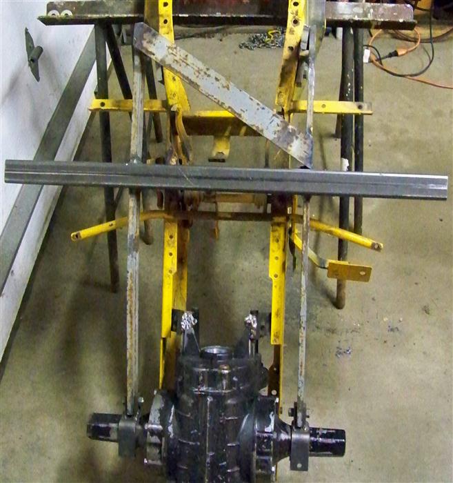
I parted out an 1862 a few years ago, and I kept the frame to use as a jig for creating attachments. It was very handy for this project, as there's really no way I would have been able to weld it together on the tractor or just on the bench. Another thing I discovered is fairly loose tolerances in the frames. At times, what fit this frame perfectly would barely fit or not fit at all on the 682's frame.
Anyway...for awhile before I started this project, I collected pictures of loader subframes, and I don't think I ever found two that were alike. There were probably very few loaders made that originally came attached to a Cub Cadet, so most people that buy one are forced to build a subframe, and most of them don't know what they're doing. I saw a lot of things I didn't like on many of those subframes, so I was on my own for this. The subframe consists of two 1/2" x 2" pieces of steel that run the length of the subframe. The subframe connects to the rear axle and to the frame. I have seen several subframes that have no connection to the transaxle, and I do not feel that is a good idea. This design transfers part of the load directly to the axle, which should stress the frame less.
This is what I came up with to connect the subframe to the axle tubes. Each side has a fork that fits over the axle, and it is made to follow the shape of the axle tube, which is a tapered hexagon. There is a large contact surface between the forks and the axle. I hope this prevents damage from occuring to the aluminum axle tubes.
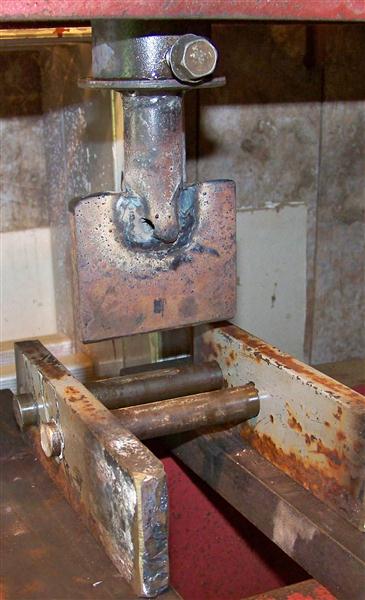
I made this device to bend the steel for the forks in a hydraulic press. It worked great, but I still wound up slitting the middle of the fork open and re-welding it together so that it would match the taper of the axle tube.
I added two crossbraces between the engine mount rails from the 1250, and then I quickly painted the whole thing to keep the welds from rusting. I used four good engine mount rubbers from the 1250 on the bottom, and I used new sway bar bushings (from a 60's GM car) for the upper ones, as is recommended in some places as a cheaper alternative to the expensive OEM ISO-mounts. After driving the tractor a bit, I don't really like these; there's a bit more vibration than I like, and the engine moves around because the old mounts are rather soft. I will probably get a second sway bar kit and put those on the bottom. It probably will vibrate more, as the sway bar mounts are not designed for this purpose. When I graduate from college and start making money, I'll buy the correct OEM mounts and do it right.
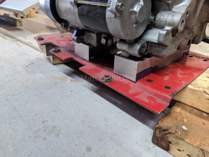
I installed the engine cradle and put on the riser mounts. Now the engine lines up with the driveline. I later discovered that measurements I obtained from someone for the fore/aft location of the engine were incorrect, and my engine is farther forward than it should be. I'm not really concerned about this, as nothing interferes, and the pulley for the pump actually lines up better this way. Also, notice the fuel pump-- Since the bottom of the fuel tank on the 82 series tractors is below the carburetor, a fuel pump is necessary. I cleaned up one of the old metal-body pumps I had and am using it. It works, but I think I will ultimately add an electric fuel pump so I can turn the pump on for a few seconds to fill the carb with gas without having to crank the engine.
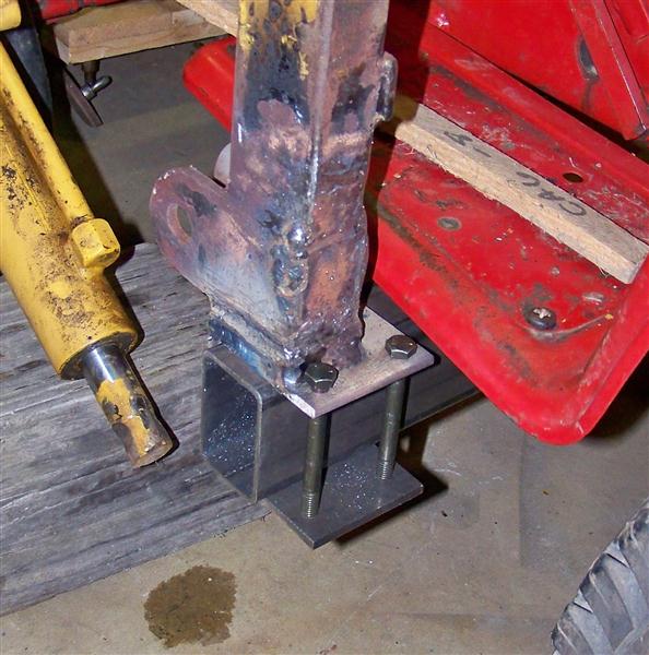
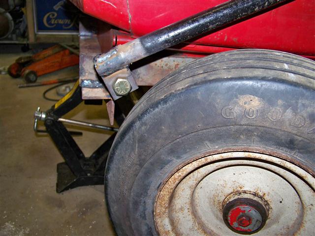
I added a 1/2" thick piece of steel between the C-channel and loader upright to create some more space for the front tires. This is how the uprights are clamped to the 2" x 3" rectangular tubing on the subframe.
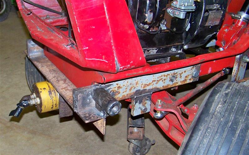
Initially, I planned to use an old mule drive for the front mount, but then I realized it would be easier to start from scratch. This piece serves two purposes. First, it is where the hydraulic pump attaches, and second, it is where the braces to the uprights connect. Four 1/2" bolts and a 1/2" rod through the QA horns connect it to the frame. I remove the QA bolts and bolted this piece directly to the frame, and I also put bolts through the two additional holes in the frame. It isn't shown in the picture, but I had to countersink the forward hole on the left side and use a countersunk bolt so that the steering knuckle would clear it. The pump has four 1/4" holes for mounting, and I put four corresponding slots in the bracket to allow me to tension the belt. I do not have a milling machine, so I had to make the slots by drilling a series of holes and filing between them. It took forever, but it is hard to tell they were not made with a milling machine. Not shown are the gussets I added to strengthen the area where the braces attach.
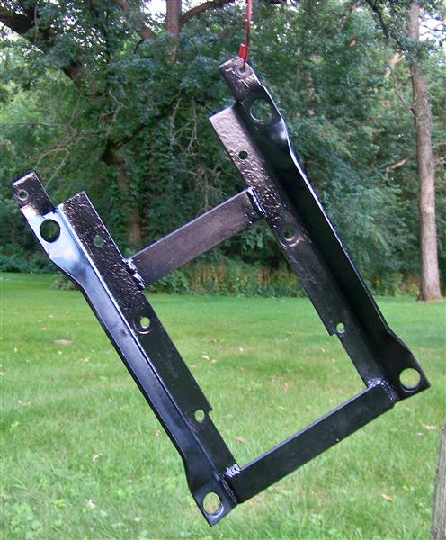
This is the completed subframe. I added one diagonal brace for added strength. It is not visible in the picture, but the lengthwise pieces of the subframe pass through slots cut in the rectangular tubing. This is much better than if the lengthwise pieces were just welded to the walls of the tube. Applied loads would eventually deform or crush the wall of the tube, which is bad for obvious reasons.
This is how the brace attaches to the front bracket. The other end attaches to a bolt at the top of the loader upright on each side. Some loaders I have seen don't have these, but I feel that they should. With these braces in place, the twisting moment applied to the rectangular tube of the subframe is reacted and transferred to the frame, instead of having to be completely absorbed by the loader subframe. Before finish-welding the braces, I jacked up the front of the tractor and verified that I had tire clearance with the axle and front wheels in any position.
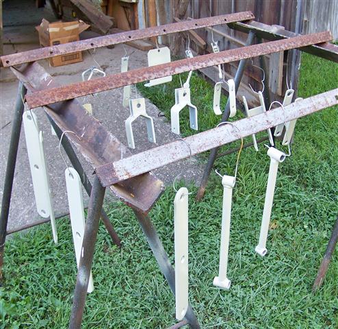
I decided to scrape off as much of the paint as I could and just repaint the whole thing. I used Valspar primer and IH White with hardener, shot with a Harbor Freight HVLP gun. It isn't bad paint for the low cost (about $9/quart); I don't like to use expensive paint on something I know is going to get scratched up again. It took about 2/3 of a quart of primer and 2/3 of a quart of paint. I can never understand why people have such an aversion to painting with a spray gun; it doesn't take much practice to become reasonably good, and it would take dozens of $5 rattle cans to put on the same amount of primer and paint that I have less than $20 in. The savings would pay for the $30 paint gun the first time it was used. This is more expensive up front, but much cheaper in the end. The quality of the finish is also much nicer.
I should also mention a few things other Kwik-Way loader owners should be aware of; as I was cleaning rust and paint off of the parts, I found that the bushings that were welded into the frame for the bucket pivot had broken loose and had to be welded back on. One of the uprights had a worse problem; the bushing in the pivot had completely disintegrated, and I had to weld in a new one. If the bushings are missing, the pivots will wear and get loose very quickly.
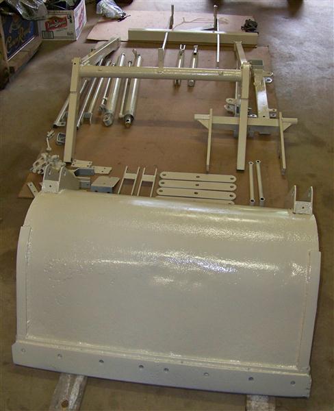
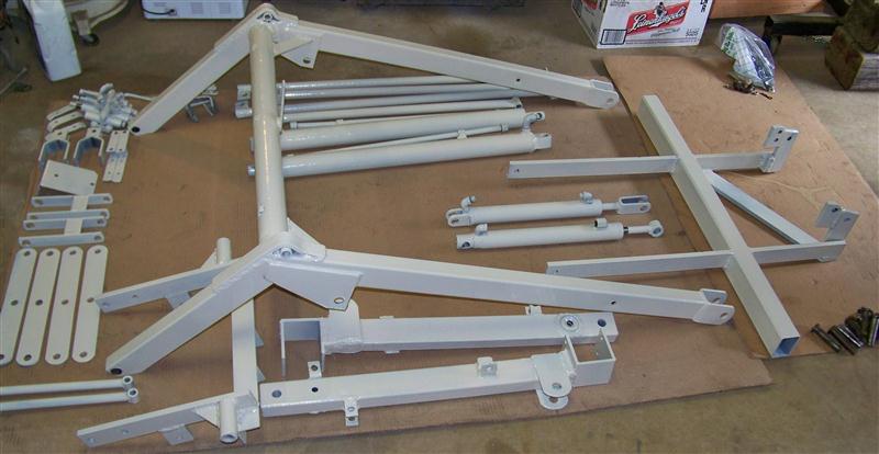
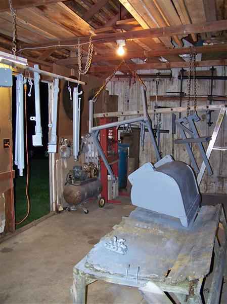
Here are most of the parts of the loader laid out on the floor. It took about two days to reassemble everything. Every time I put something together after I paint it, I remember why I hate fresh paint: it does not have the hardness of 30-year-old paint, and it scratches and scuffs so easily.
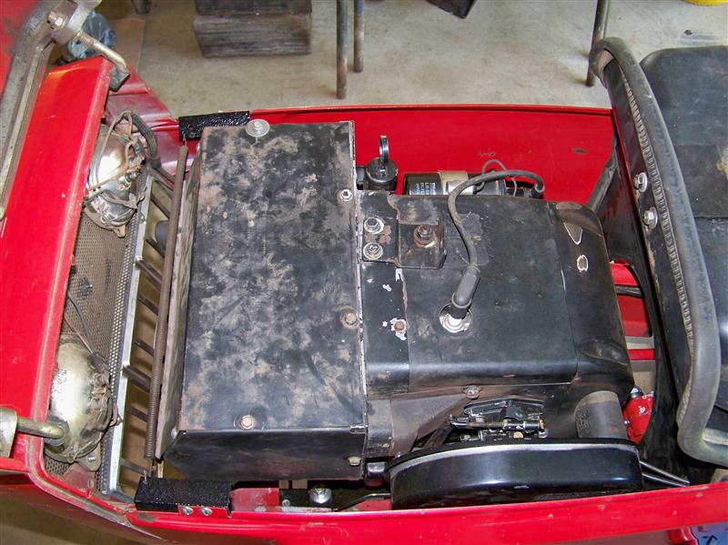
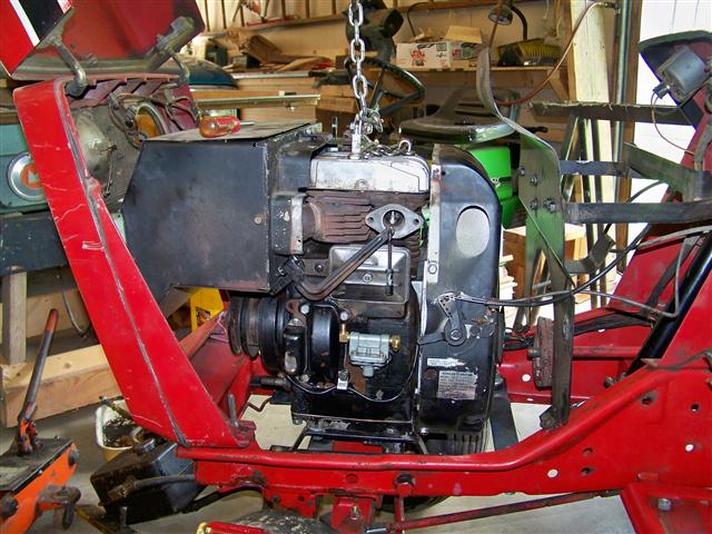
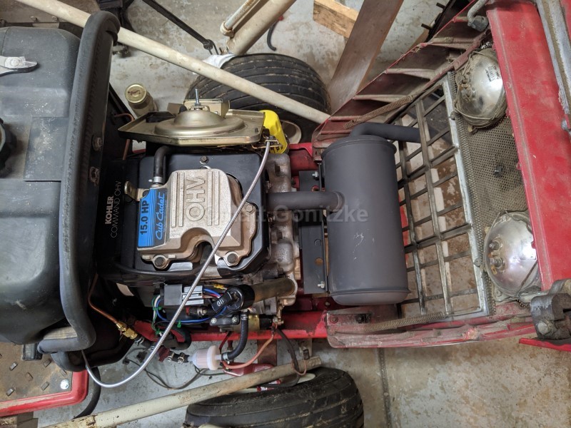
This is the engine installed in the 682. There is plenty of room to work on the engine once the side panels are removed. This is one reason why I wanted a single-cylinder engine; the twin cylinder engines are hard to work on in the tractor, even when there isn't a loader in the way. This tractor absolutely has to be easy to work on, as if it fails to start where it sits, it cannot be moved and has to be repaired where it sits.
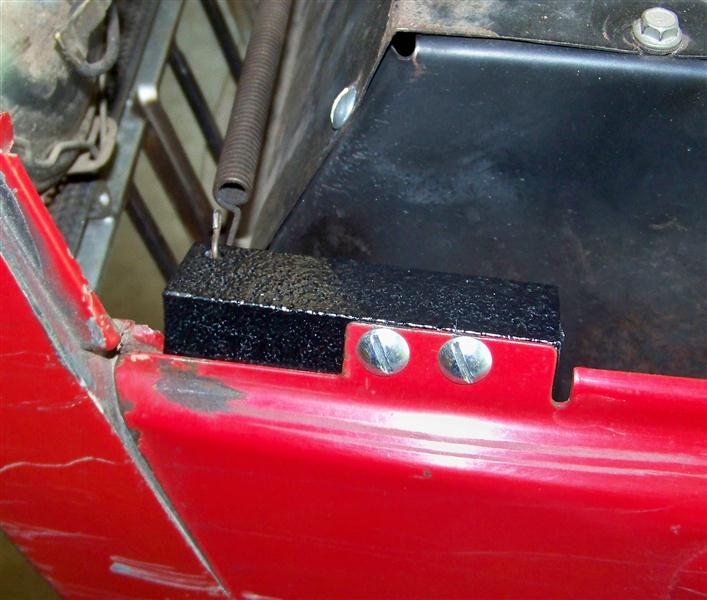
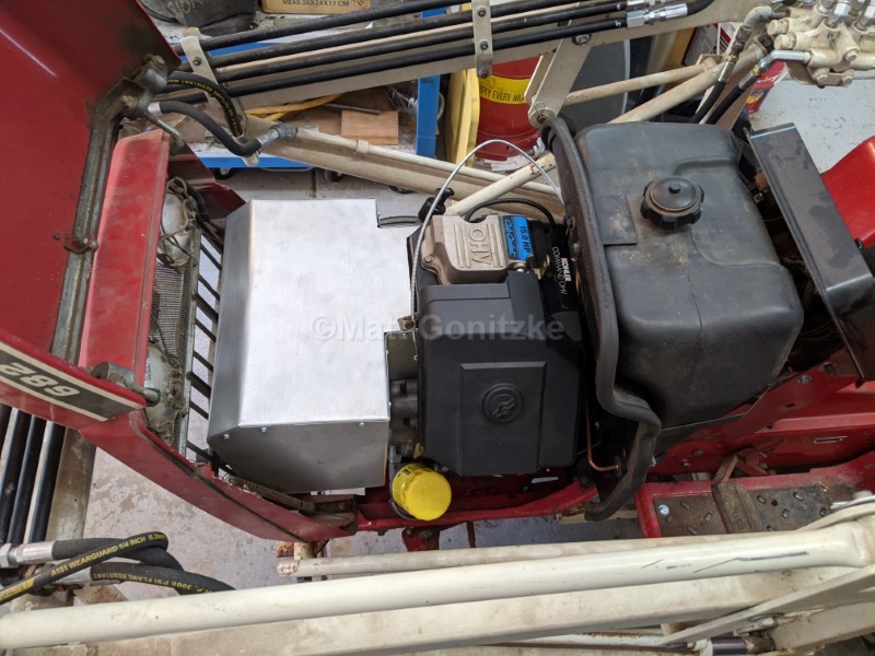
I also found that the side panels on the IH-built tractors, like this 682, will not work with the single-cylinder engine. I added two small pieces of angle iron to move the spring further forward so it clears the muffler box.
Here it is, finally finished! After I put it all together, it didn't work. After two days of troubleshooting, I found that the relief valve on the control valve was set at about 75 psi. I adjusted it to about 800 psi, and now it works great. I added 150 lbs. of wheel weights. It should be all ready to use now. This took much longer to finish than I imagined; I started the first week of July and finished the third week of August.
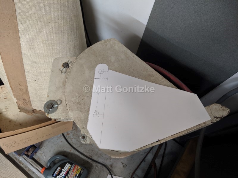
Fast forward to 2019...this thing sat unused for nearly 10 years until I finally decided I could use it for things around my yard at my house in Kansas, so in July 2019 I moved it from Illinois down to Kansas and started fixing it up again. First, I fabricated a new, smaller bucket more appropriate for moving earth, rocks, etc. than the snow bucket. In my opinion, these tractors are still a bit light for a loader, and if you make them heavy enough to do serious work, you start finding the weak points. By making a smaller bucket, I hope to make it difficult to damage the tractor. This picture shows the template for the new bucket on top of the old one, for comparison.
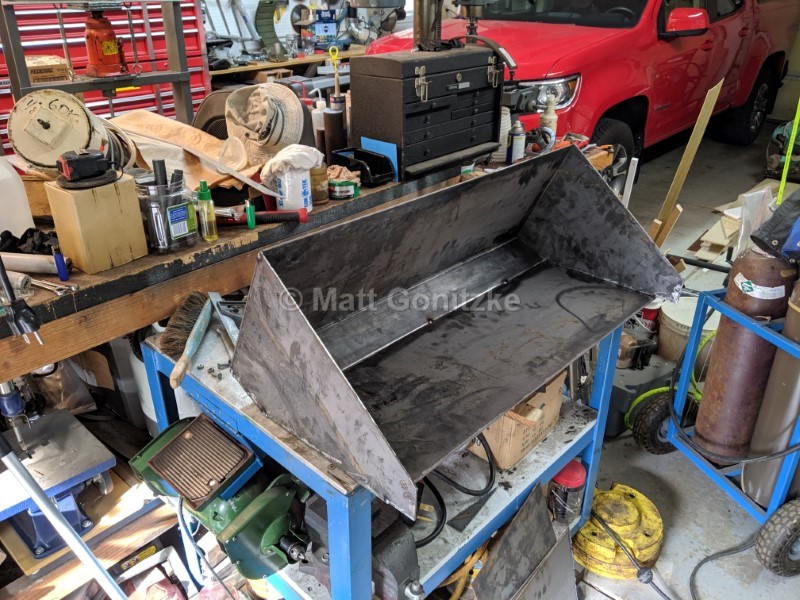
The finished bucket. Cost about $150 in materials and quite a bit of time. What can't be bought must be built...
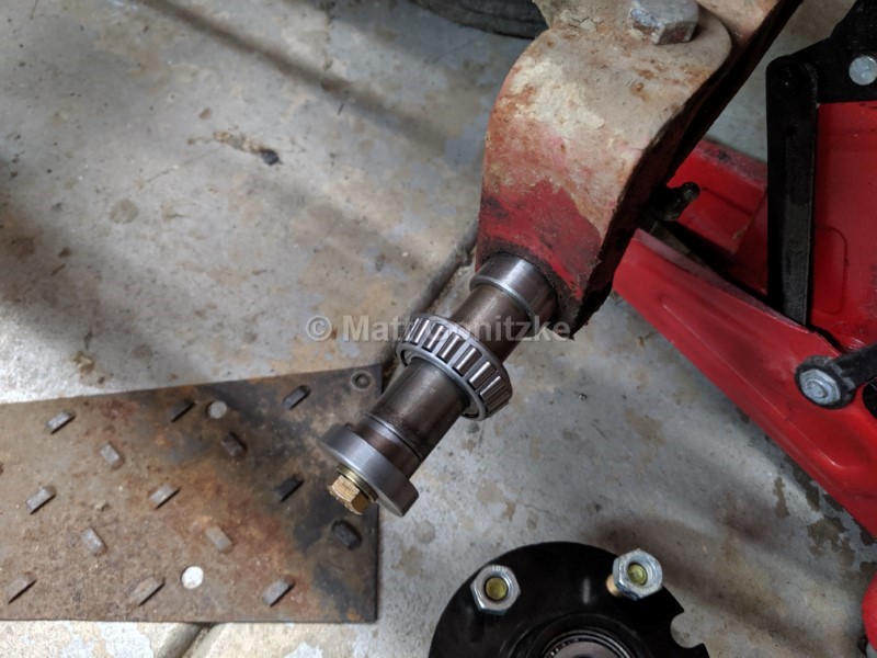
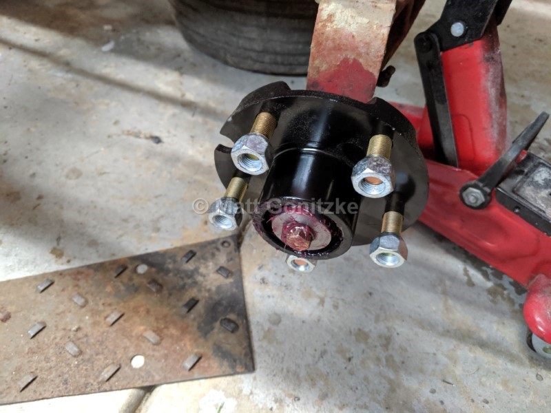
Next, a couple of necessary mods to the front spindles. First, even the 1" front spindles do not have enough load capacity in the OEM bearings. The easy fix for this is a pair of "shorty" trailer hubs and tapered roller bearings. They are still too long for the spindle, so I machined a spacer/end cap to slightly lengthen the spindle, retain the bearings, and preload them. It was machined to a precise length as to preload the bearings correctly when properly tightened. I replaced the original wheel retaining bolt with a grade 8 bolt, as there is quite a bit being asked of it.
Here's how it looks with the hub installed.
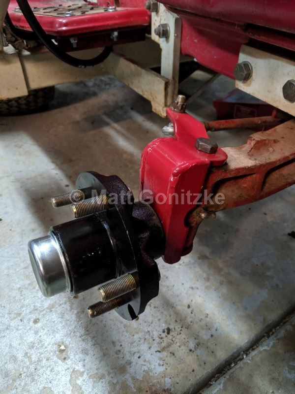
The other necessary modification is the addition of a couple of pieces of metal to turn the flat plate portion of the spindle into a C-channel. As manufactured, the spindles are not strong enough for a loader and WILL eventually bend. This makes them quite a bit stronger. The weak point is now likely the steering box.
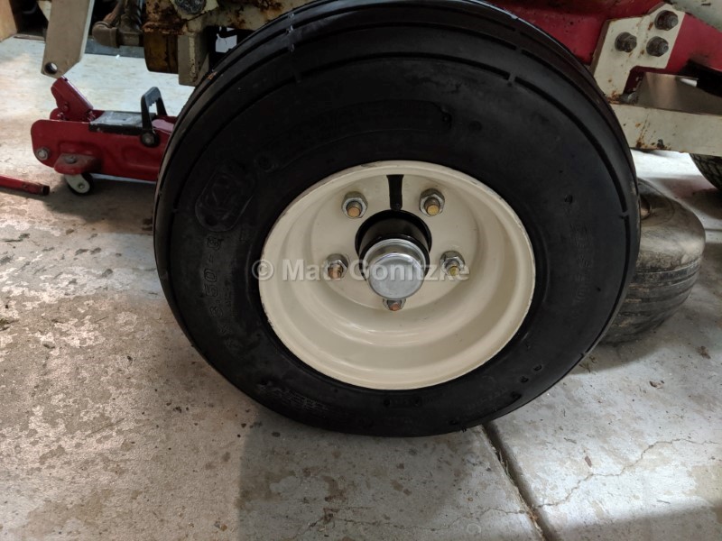
I bought some 8" trailer wheels of the appropriate offset (similar to OEM), painted them IH white, and mounted a new 4-ply smooth rib tire for ease of steering, and inflated them to the sidewall maximum of 28 psi, which is the pressure for the rated load. 2 ply tires do not have a sufficient load rating for the front of a Cub Cadet with loader.
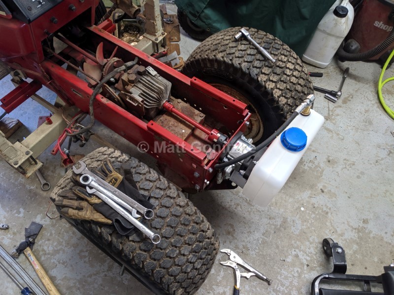
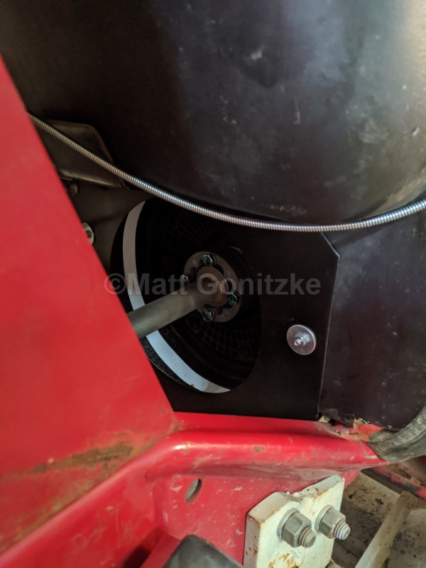
Next, I replaced the original pump (it was far too small) with a new ~4.8 GPM pump from Surplus Center. I raised the fenders 1" to gain access to the rear of the hydro input shaft, and made a driveshaft to couple the hydro unit to the loader pump. On the front, I made a solid coupler similar to the older metal couplers used on the gear drive tractors, and used a standard Lovejoy coupling to connect to the pump. I spent a lot of time making sure the pump would be properly aligned as to not tear up the driveshaft. So far, so good.
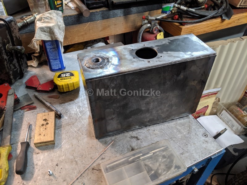
The plastic tank in the previous photo did not work out- I had to place the suction fitting over a seam on the tank, and I couldn't tighten the bulkhead fitting enough to get it to not leak, so instead, I bought some material, bungs, and a filler cap, and welded up my own tank. It took a few tries to get it not to leak. To leak check it, I made a blockoff plate for the filler neck, capped one bung, and hooked up 5psi air to the other bung and sprayed it with soapy water. I was then able to identify pinholes, weld them, and try again. After a few tries, no leaks.
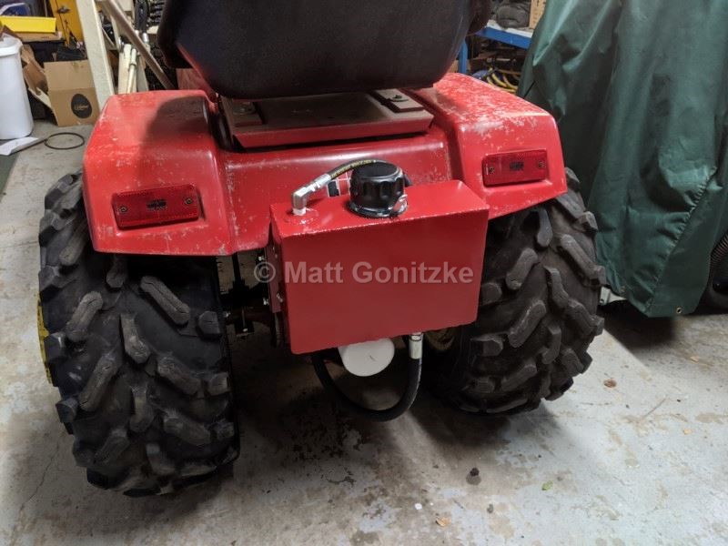
The installed hydraulic tank. The return line has a standpipe in it such that the oil returns to the tank below the surface, which helps prevent foaming.
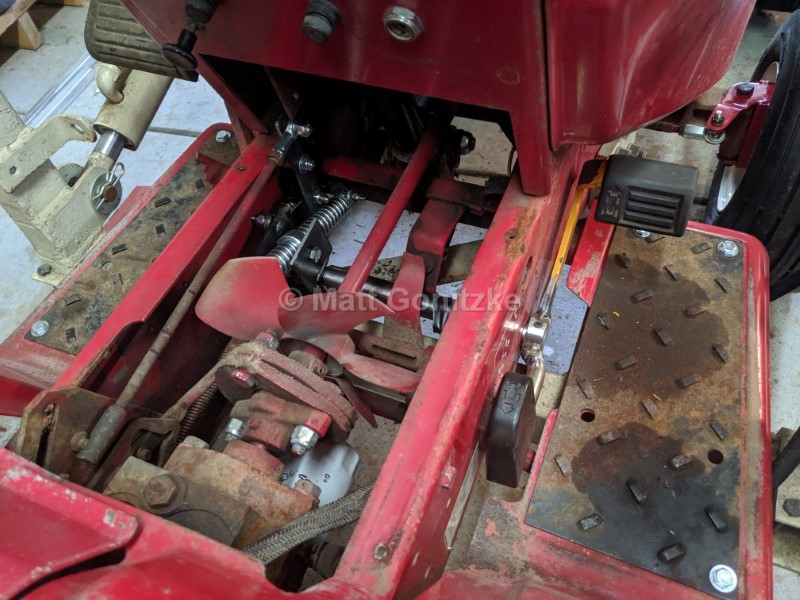
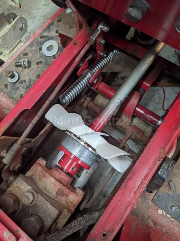
I also added a foot control for the hydrostatic transmission so I would not have to help steer, move the hydro lever, and run the bucket controls with one hand.
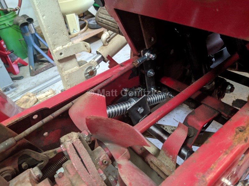
The mechanism uses a pair of springs for centering. It works fairly well. The shaft onto which the pedals are mounted is installed in place of the lift rockshaft, since this was a manual lift tractor, and the lift is useless on a dedicated loader machine.
I replaced all of the hydraulic hoses and a bunch of questionable fittings, as hardware-store pipe fittings are not strong enough for this application. I also bought and installed some used ATV tires, tubed them, and put 6 gallons of washer fluid in each. At some point, I need to replace the control valve, as the tilt sags very quickly.
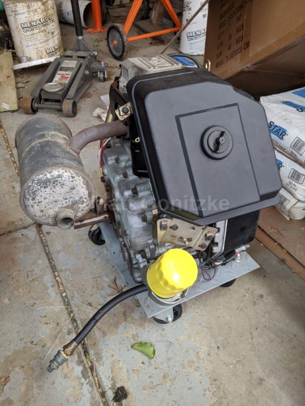
In the spring of 2020 I found a CH15 from a Cub Cadet 2155 and bought it to replace the very tired K321. I was a bit leery of buying a non-running engine, but the price was right ($50) and it came with a PTO clutch and driveshaft; I sold the former and modified the latter to work in here. These single-cylinder Kohler Commands are nice engines; they are overhead valve, sip fuel, and have full pressure lube and an oil filter.
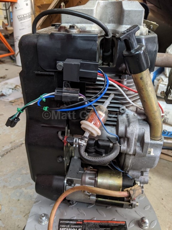
Since the 682 is wired for a battery ignition engine, a relay is required to use the ignition wire to un-ground the ignition module when the ignition is on. I made a wiring harness with Packard 56 connectors that plugs into the existing tractor harness, as well as the engine harness.
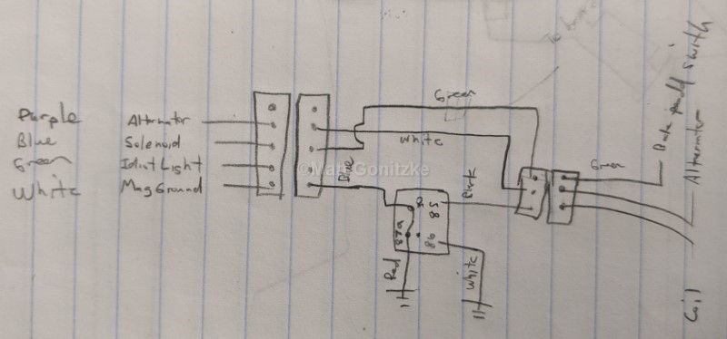
Here is a diagram of the additional relay and wiring necessary to connect this up without any permanent modifications to the tractor.
I made some aluminum spacers, bolted them to the engine, and then bolted the spacers to the original engine mounting plate, using existing holes. I located the engine such that if I had wanted to use a PTO clutch for some reason, it would be in the correct fore/aft location.
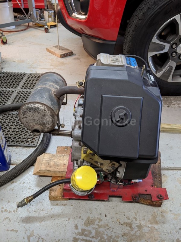
Here is the engine mounted to the mounting plate, with the muffler being test-fitted. I couldn't find any existing muffler that would work for this application, so I bought a used John Deere LTX38 muffler on eBay (fits the vertical shaft version of this engine) and modified it so the muffler exit would fit through the grille. This is visible in some of the later pics.
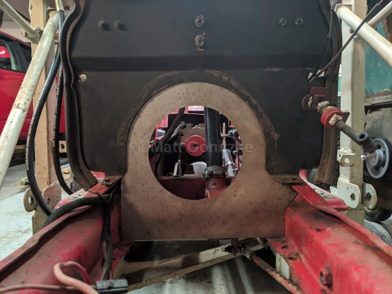
To ensure the engine would cool properly, I added an extra piece to the firewall to make sure the engine is drawing cooling air from behind the firewall, and not recirculating hot air from inside the engine compartment.
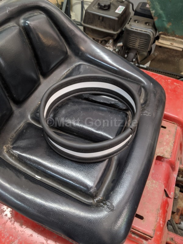
I also added a duct with a bulb seal on each end that gets wedged between the firewall and the flywheel shroud.
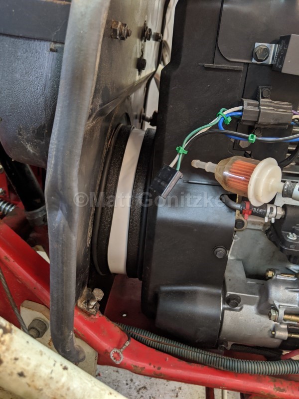
This photo shows the installed duct.
At this point, I have everything fitted, and I just need to modify the muffler and add a heat shield.
I shortened the driveshaft that came with the engine (procedure described in detail in the "1872 #2" page) and installed it. I really like these driveshafts. They should be a lot more maintenance-free than the original 82 series driveshaft.
This picture shows the engine end of the driveshaft, as well as the modifications to the firewall described previously.
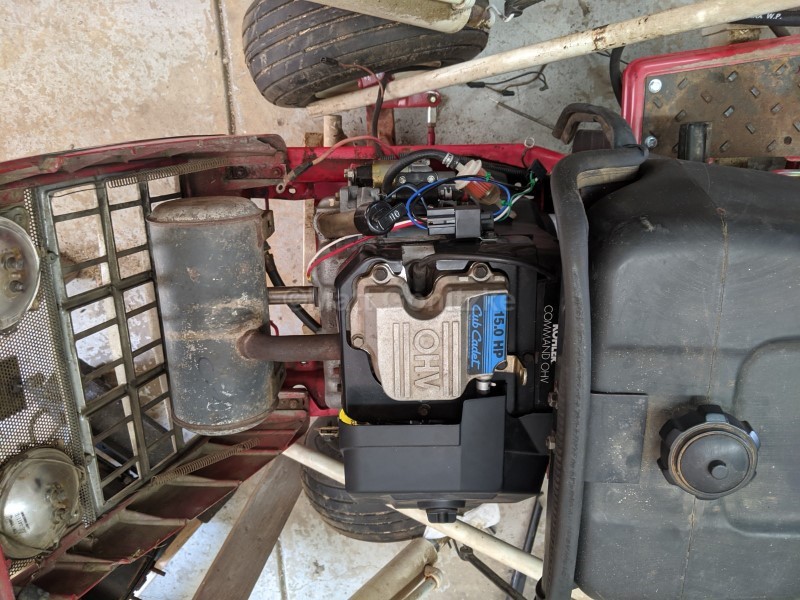
Here is the final test fit with the muffler modified, painted and installed. The last step is to create a muffler heat shield to protect the headlights from heat and direct the cooling air out the front of the tractor.
Due to stores being closed for COVID, my options were a bit limited for heat shield materials. I ended up using some galvanized steel sheet instead of bare steel sheet painted with high-temperature paint. That's it! The final installation ended up pretty clean. This engine is not particularly compact for what it is, and there is barely enough room down at the bottom. This would be a very difficult engine to retrofit into an older tractor.
After having spent a lot of hours in 2021 and 2022 operating the 682 with the new engine, I couldn't be happier. It barely uses any fuel, and it starts reliably and has plenty of power. I need to add an electric fuel pump, as it takes quite awhile for the mechanical pump to prime when the tractor has been sitting for a couple months. I also plan on adding an oil pressure gauge one of these days, since that is a good way to monitor the engine temperature as well.