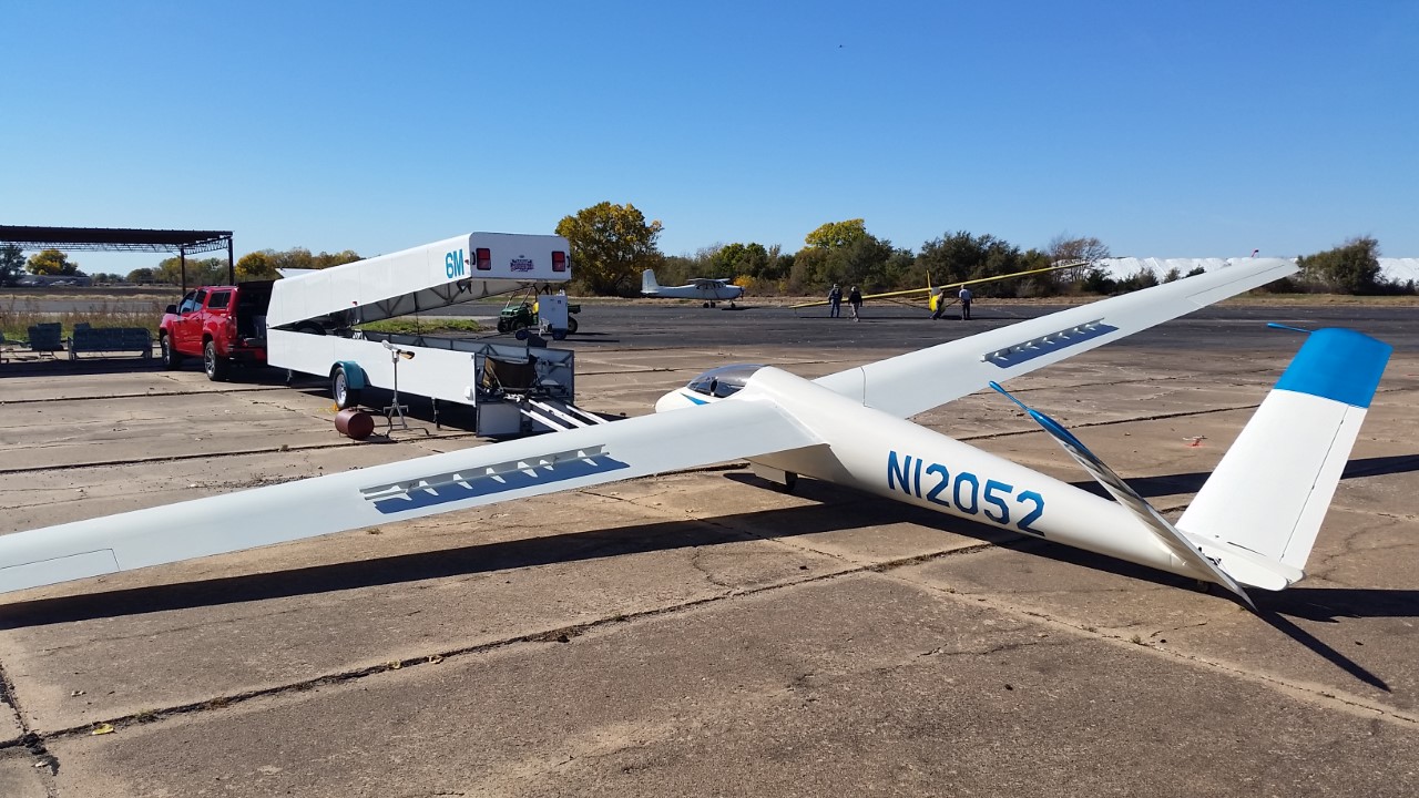
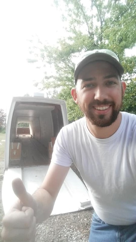
When I purchased my SH1, it came in a wooden Kuhn trailer that was built in the early 1980s, and it was starting to show its age. I had issues with the front hatch leaking in the rain, and I found myself constantly repairing and repainting small areas. The trailer was also only as big as it needed to be, which made rigging and de-rigging the glider without damaging it rather difficult. Plus, the wing roots were at the back of the trailer, which made the use of a rigging aid difficult, thus requiring several strong, experienced helpers. This severely limited my flights in the glider. I decided to build a new trailer similar to a modern Cobra (or similar) clamshell trailer.
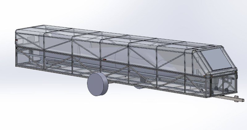
In 2016, I started doing research and collecting information. Another member of our soaring club gave me a partial set of Luebke trailer plans, along with some suggestions as to areas that needed improvement, in his opinion. I ended up using those plans as only a rough starting point for tubing sizes and structural layout. I spent 2016 and 2017 slowly designing and modeling the entire trailer in SolidWorks, a 3D CAD tool for which the student version is free to use for Experimental Aircraft Association (EAA) members.
Jump to section:Throughout the design process, my goals for the final trailer were as follows:
The basic sizing of the Luebke trailer was my starting point for this trailer. The trailer is sized such that uncut (in width, at least) 4x8' sheets of 3/4" thick material are used for the flooring. The lower chord of each ladder frame making up the sides is 1 3/4" x 0.120" wall steel square tubing, and essentially all interior members are 1" steel square tubing. The vertical supports between the upper and lower chords of the ladder frames are nominally at 48" spacing, but this was adjusted slightly for proper sheathing overlap. The lateral supports for the floor are at 24" spacing nominally, adjusted to work around the axle and various other required hardpoints on the floor.
It has been my observation that most homebuilt glider trailers are either extremely over- or under-built. The Luebke design seemed to mix both of these things together in different areas, so I ended up using a variety of tubing wall thicknesses in the lower half of the trailer. My local steel supplier had 1" steel square tubing in 0.063", 0.085", and 0.120" wall thicknesses. I used 0.120" wall tubing for the four corners and front vertical members of the bottom of the trailer, as well as the lateral members supporting the floor. 0.085" tubing was used for the other verticals and the upper chord of the ladder frames, and 0.063" was used for the diagonal bracing of the ladder frames.
Another common weak point among homebuilt trailers that was brought to my attention by several people I talked to was the tongue. Most are undersized and eventually suffer cracks at the attachment points. To alleviate this problem, I used an 8' length of 3" x 3/16" wall square steel tubing for the tongue, and attached it in three places under the trailer.
I maximized the height of the sides of the bottom of the trailer in an attempt to minimize the weight of the clamshell top. The sweet spot for this resulted in the height of the sides on the trailer lower frame being 22.5" from the surface of the floor to the top surface of the upper chord of the frame.
The top of the trailer is constructed with 1" x 0.080" wall aluminum square tubing, riveted together with structural pop rivets and gusset plates. It and the sides of the lower portion of the trailer are skinned with 0.032" aluminum.
As I modeled all of the parts in Solidworks, I also developed a large Excel spreadsheet to help me estimate and track weight and cost, determine axle placement, size the hatch and clamshell hinges, build cutting lists for the raw materials, and various other things. A rough model of the glider itself was also created in Solidworks to help ensure that the glider would actually fit properly once the glider was constructed. This was aided greatly by a Schempp-Hirth factory trailer handling drawing that happened to come with my glider, having survived through 13 owners over the last five decades. After what I estimate to be between 500 and 1000 hours of design spread over 2016 and 2017, I was finally ready to start building the trailer.
Prior to the start of construction, I invited three glider pilots from our soaring club to my house, and I walked them through the design of the trailer, allowing them to make suggestions for things I might changed or improve before construction. Collectively, these three individuals represented nearly a century of experience with gliders and glider trailers. I wanted to be happy with the trailer the first time, and the only way to do that was to use the collection of things all of them had learned over the years. Some relatively minor tweaks were made, and I started preparing paper drawings to use to start producing each of the 600+ individual parts that comprised the trailer. Solidworks makes it fairly easy to produce dimensioned drawings from 3D models, so I made a bare-bones set of drawings that was enough for me to build all of the parts. By this point, it was January 2018, and I was ready to start. I estimated a cost of $6000 and 500 man-hours to complete the trailer. I hoped to be done by June and still be able to enjoy the latter half of the soaring season.
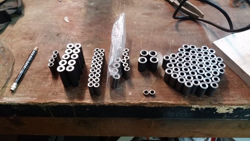
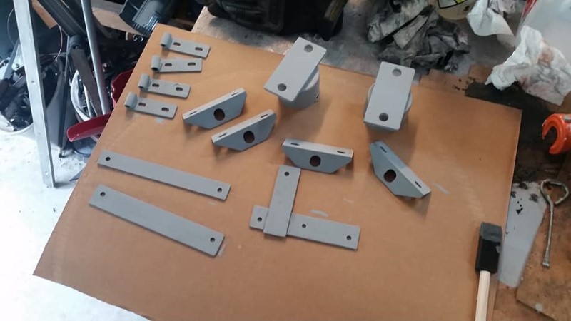
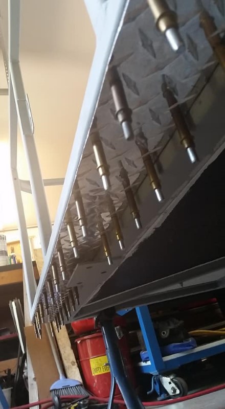
After spending several weeks making and printing paper drawings, and then sourcing material from a variety of choices where I live near Wichita, Kansas, I started cutting metal in February 2018. The first task was to make well over a hundred steel bushings that would later be welded into the tubing structure anywhere a bolt passed through. This would both ensure that tightening the bolt would not crush the tube, as well as seal the inside of the weldment from the elements. Several featured a blind threaded hole instead of a through-hole to allow me to install fasteners in areas with poor access to both sides after assembly of the trailer. A couple of days on the lathe, and I had most of the bushings I would need for the lower weldment.
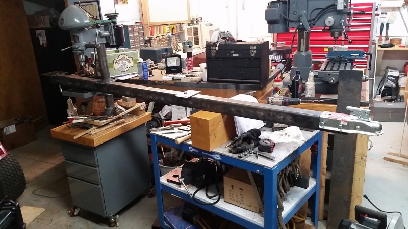
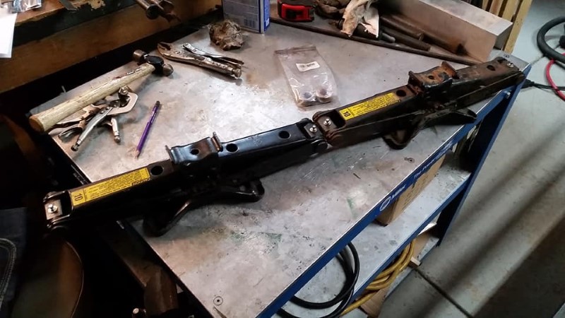
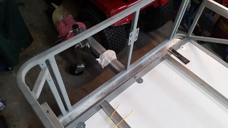
I started construction of the main portion of the trailer with the tongue. As stated earlier, it is 3" x 3/16" wall steel square tubing, which I feel is the minimum size for it to have a near indefinite life in this application. Every location with a bolt passing through it recieved a bushing TIG welded into it. I also cut, drilled, and welded on the attachment plates at the three locations where it bolts to the trailer, as well as the plates for mounting the folding jack and safety chains. The tongue ended up weighing in at around 65 lbs, but it shouldn't give me any trouble.
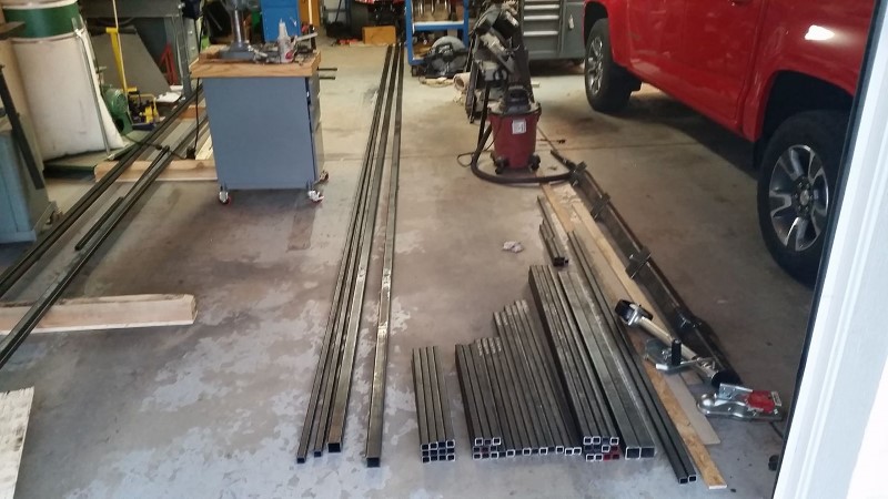
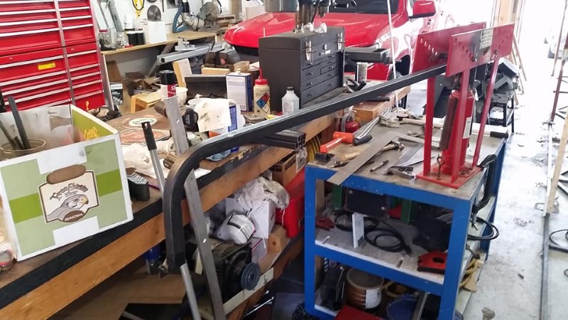
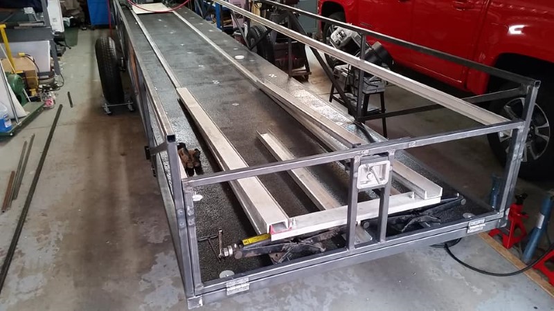
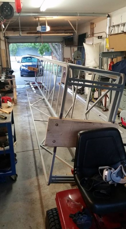
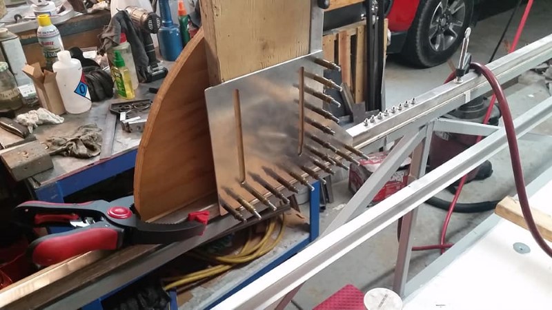
I borrowed an open Schweizer trailer and used it to pick up 20' lengths of steel tubing from a local steel supplier, shown before and after cutting all of the pieces to length in the next two photos.
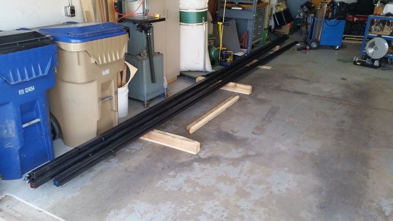
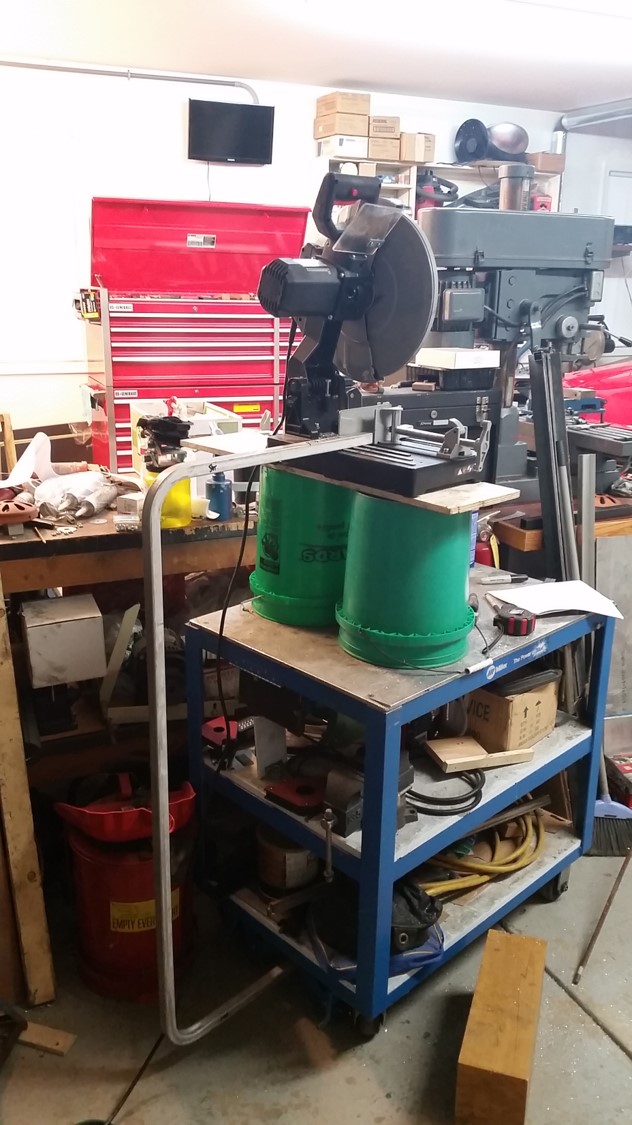
It should be noted that prior to starting this project, I purchased a 14" dry-cut metal saw (Item number 46461 from Northern Tool), knowing that I had a massive amount of tubing cuts to make, and my horizontal band saw would not be up to the task. This saw is similar to a wood-cutting miter saw, but has a larger 14" blade and turns much slower, appropriate for cutting steel. It was a bit spendy at around $250 (and replacement blades are also spendy at $80 for a good one), but this tool saved many, many hours by virtue of the fast, square, clean cuts it makes. I don't know how I lived without this thing before. It is FAR better than an abrasive cutoff saw, and I wouldn't even think about starting a project like this without one of these. Throughout the progression of the page, I'll try to make note of any special tools or other tricks that made this project easier and faster.
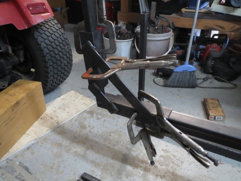
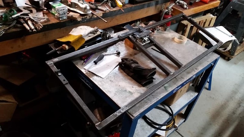
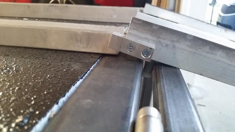
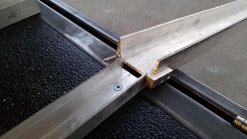
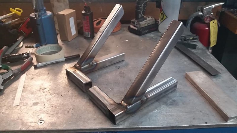
Prior to welding the trailer frame together, I made two different clamping fixtures, a 90-degree angle fixture, and a straight splice fixture. The need for the former is obvious; the latter is needed because the trailer, at 26.5 feet long, is longer than any commonly available tubing sections (20 feet), so splicing of the four chords of the ladder frames was required.
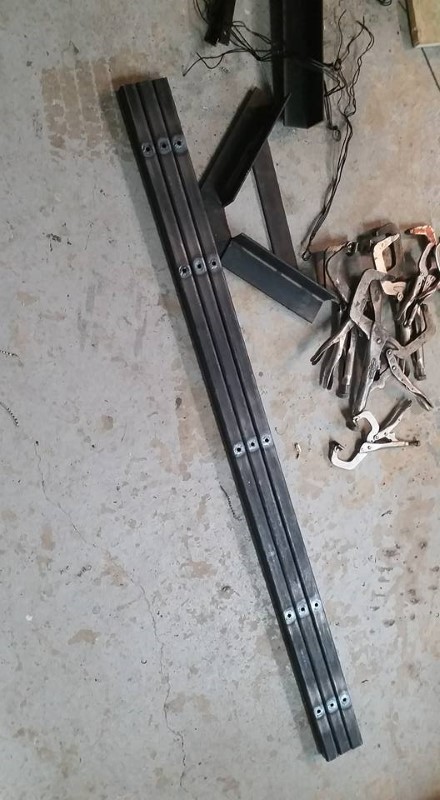
These are the lateral members that support the floor. They are 1" x 0.120" wall square tubing, and all have bushings welded in where the floor attachment bolts will go.
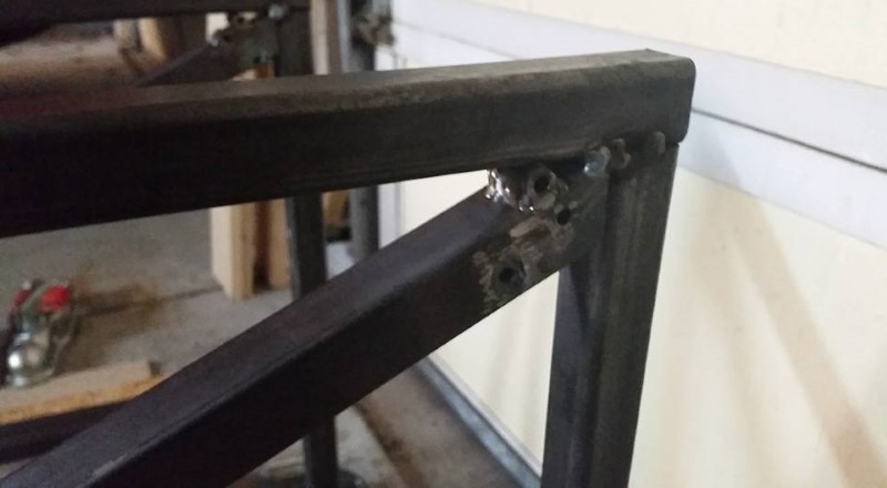
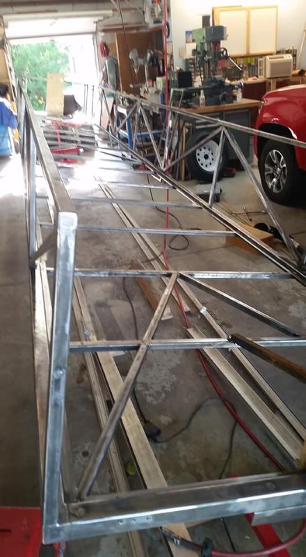
Using the right-angle welding jig picture further up, and some help from my neighbor, I first welded all of the vertical members to the bottom chord, then welded on the top chord, then filled in the diagonals. Holes were drilled in the upper and lower chords at each joint to connect the tubing interiors together. This helps prevent the heated air inside the tube blow out the end of the weld when finishing the last weld on each joint. I'll also note here that all welding on this trailer, unless otherwise specified, is done with the MIG welding process.
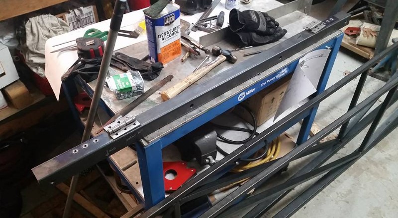
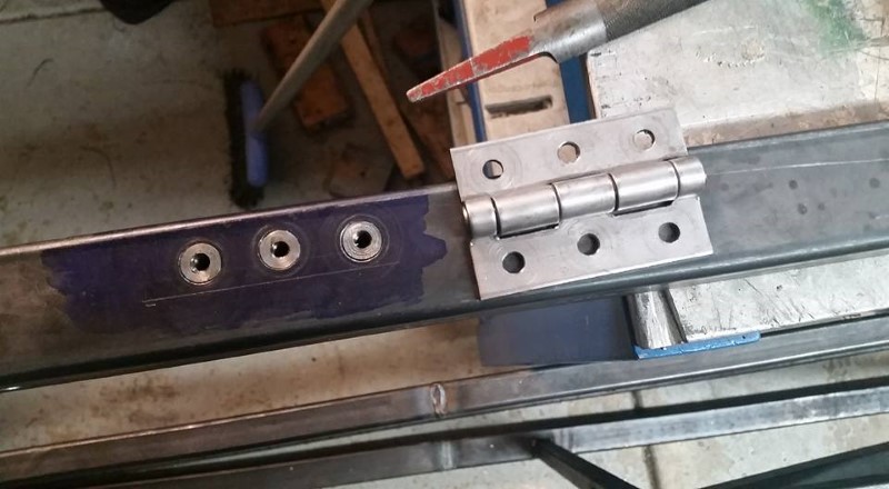
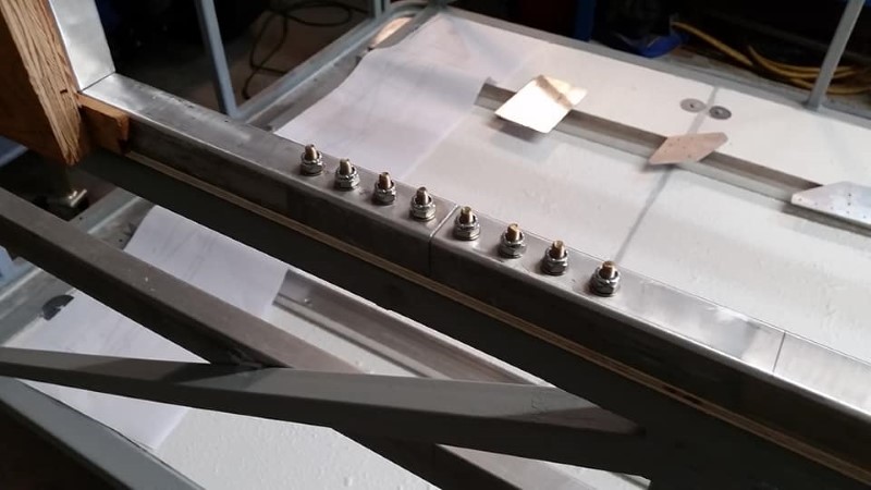
In the photo below, I have drilled the holes for the threaded bushings that will allow the hinges for the tailgate to be attached without the use of through-bolts. I purchased the stainless steel hinges "blank" (without mounting holes) from McMaster-Carr, drilled the holes, transferred the holes to the tube, then drilled the holes out in the tube to accept the bushings and then TIG welded the bushings into the tube.
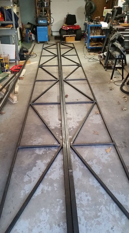
Next, with the two ladder frames complete, I laid them side by side and marked them for the locations of all of the lateral members. I created some fixtures and jigs out of scrap lumber to hold the ladder frame parallel to each other while I welded all of the lateral members in.
This is a detail view of the bushings I welded in to attach the two draw latches that are partially responsible for holding the clamshell top closed. I used draw latches from McMaster-Carr, part number 13435A320.
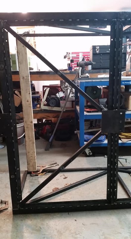
With the lateral structure under the floor welded in, I added the diagonal bracing at the axle, rear, and tongue, and then added 1" x 0.120" steel angle around what would become the periphery of each floor panel. This is to ensure that the edges of all of the floor panels are well-supported and to provide plenty of sealing area to keep water from coming in at the joints between the panels and the trailer frame. Notice that all of these angles were stitch-welded as opposed to continuously welded. This was done to save time welding and later griding the weld beads under the floor flush with the structure, as well as to prevent warpage to the greatest extent possible. Warpage is more or less unavoidable on a large weldment like this, particularly at my skill level, so I tried to avoid welding things any more than were required.
I made some dies for my hydraulic tubing bender to bend the nice rounded corners of the front of the trailer. Each tube requiring a bend was filled with sand before bending to help prevent kinking or other undesired deformation.
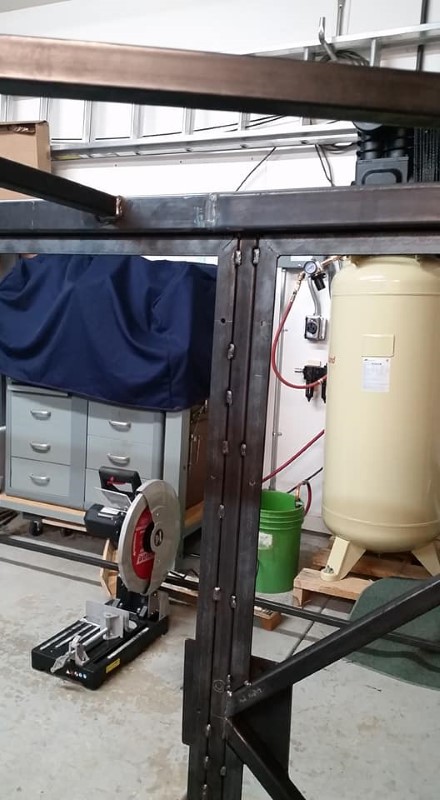
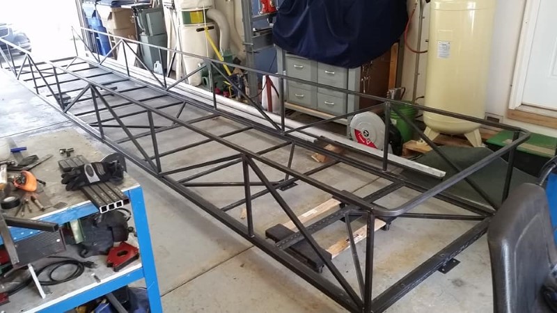
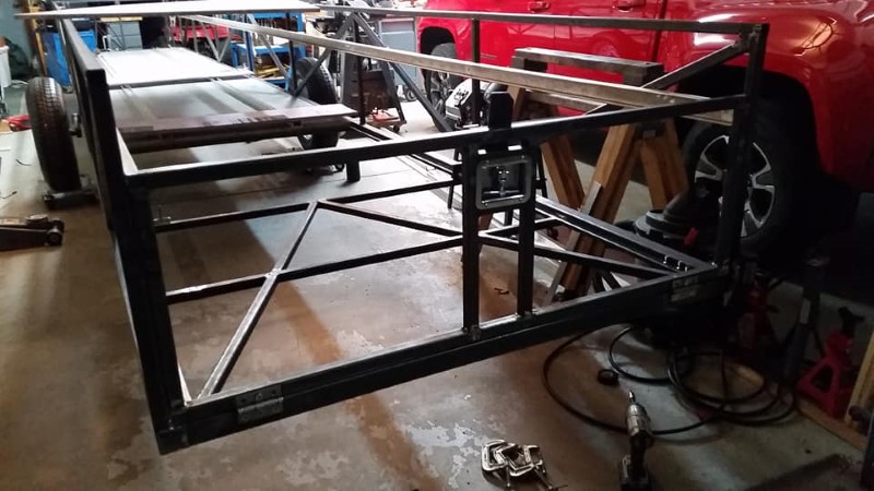
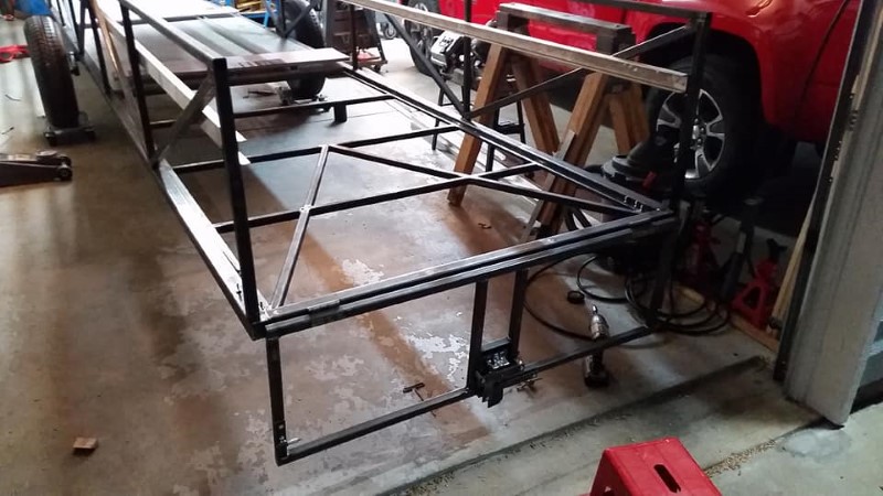
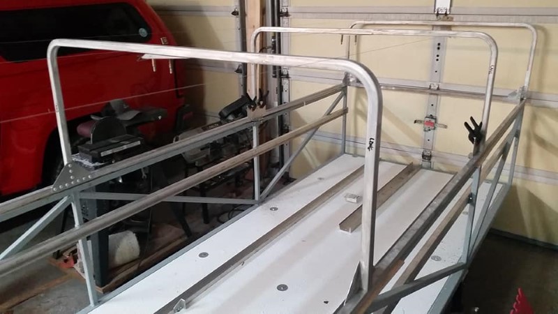
Here is the lower frame of the trailer about 95% complete. The only thing missing at this point from the weldment is the vertical supports at the front at the center and the clamshell hinge locations.
Here I have installed the five vertical supports at the front. The two to either side will support the hinge bolt for the clamshell top.
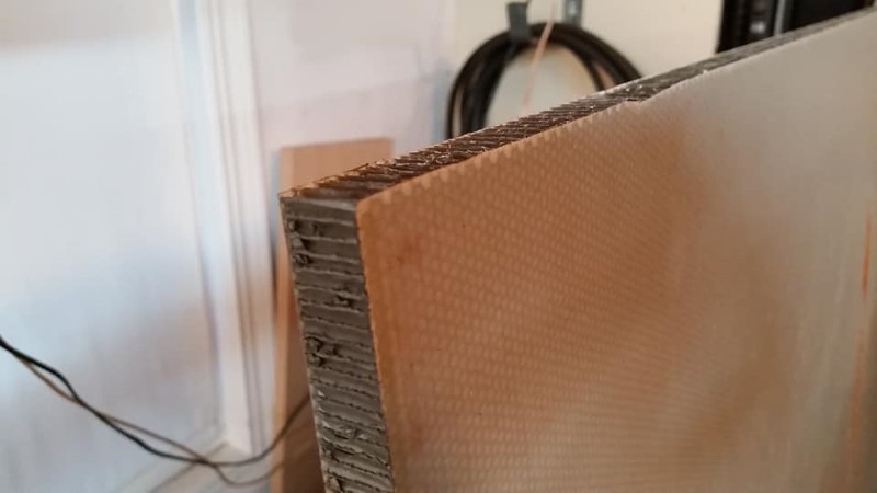
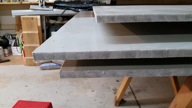
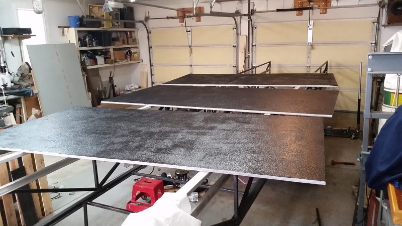
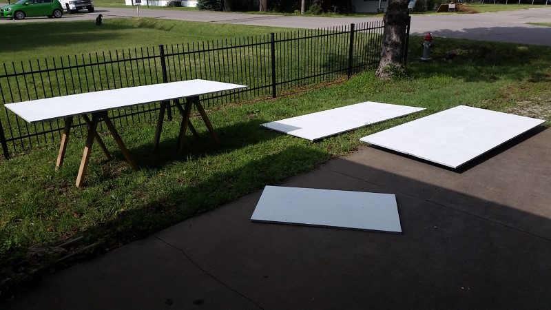
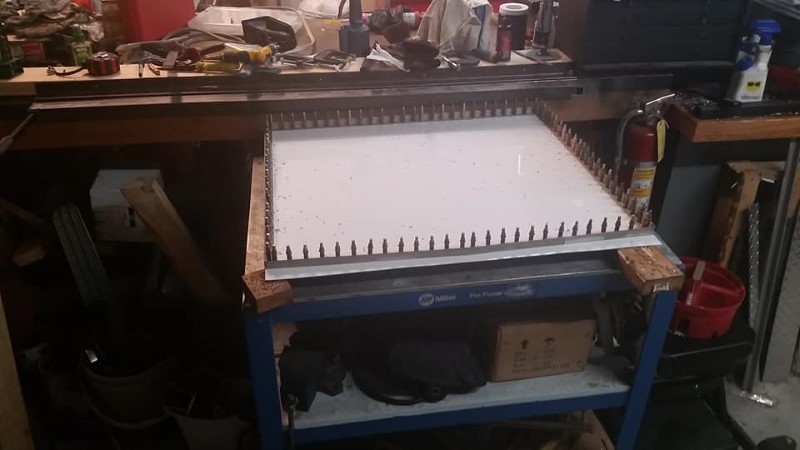
At this juncture, the axle was temporarily installed, and I had begun the process of fitting the floor. Most trailers have a plywood floor, but I have seen many rotted trailer floors, even with the use of marine-grade or pressure-treated plywood. At some point in 2016 I was at a surplus sale at Textron Aviation, and happened across a stack of 4x8' by 3/4" thick honeycomb panels for $5 each! These had been intended for floor panels in business jets. I purchased five panels, needing four for the trailer plus one spare. The panels have aluminum honeycomb with fiberglass facesheets. They are extremely light and stiff, but consequently not very damage resistant. I'll describe later how I at least partially mitigated the damage risk aspect.
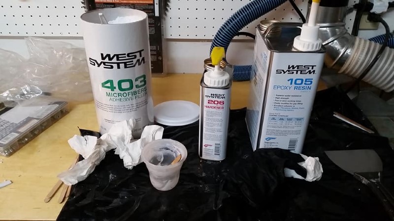
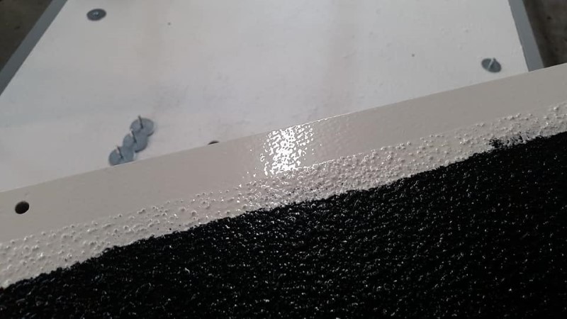
After cutting the floor panels to size and drilling all of the mounting bolt holes, I potted the edges and all of the holes with West System epoxy mixed with 403 micro. I then redrilled the mounting holes after the epoxy cured. This sealed and strengthened each hole location.
Concurrent with installing the floor, I have also test-fitted the aluminum channels in which the wing and fuselage dollies ride in the trailer. The fastener locations for the floor were designed such that these channels would also use several of the same fasteners.
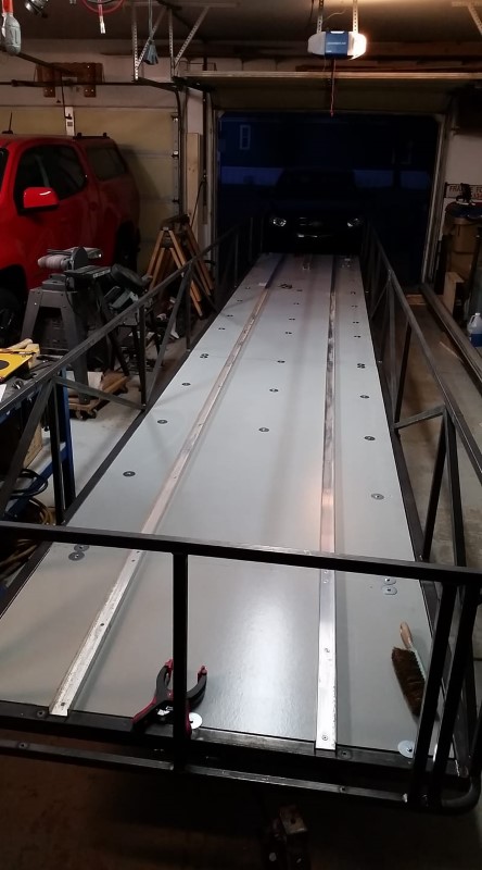
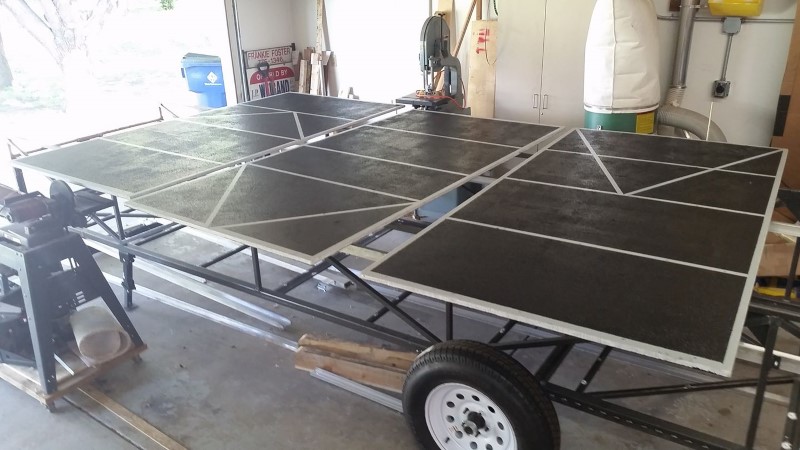
At this point, I had discovered how truly easy it was to damage the facesheets of the floor panels. Dropping a 2" long 1/4" bolt from several feet would leave a visible dent in the facesheet. After repairing several areas where I dropped bolts, wrenches, etc. while fitting the floors, I obtained some roll-on rubberized bedliner coating intended for a truck bed, and applied this to the top of each panel. The idea is that the rubberized coating spreads out and partially absorbs the shock load from a dropped object. It does not make the panels impossible to damage, but makes it much more difficult.
With the floor fitted, I turned my attention towards welding up all of the pieces for the tailgate. Similar to a Cobra trailer, it is hinged at the bottom, folds down, and also has a lockable latch for the clamshell top.
These next two pictures show the tailgate both closed and opened. Note that the tailgate is not the full height of the sides of the bottom; I had to make it this way so that the tailgate could fold 180 degrees open. This is necessary for a function of the ramp assembly onto which the fuselage rolls out of the trailer.
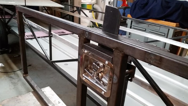
I found two of these recessed locking latch mechanisms at a local surplus store (The Yard Store). I fitted a latch arm that interfaces with the clamshell top. A slot was later cut in the tab once the top of the trailer was partially complete and the location of the slot could be determined.
On either side of the tailgate just below the upper wing dolly rails, I installed a spring loaded latch to hold the tailgate closed.
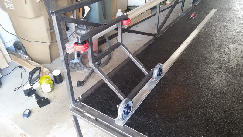
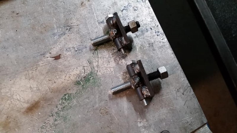
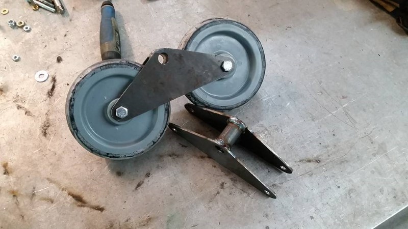
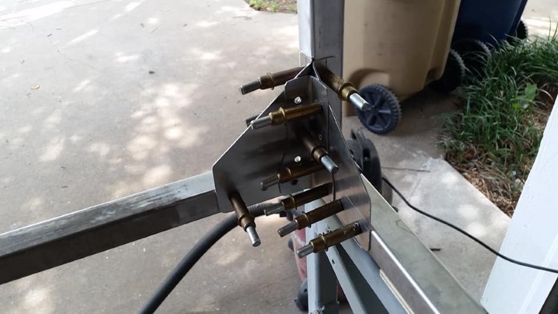
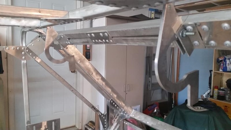
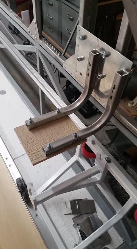
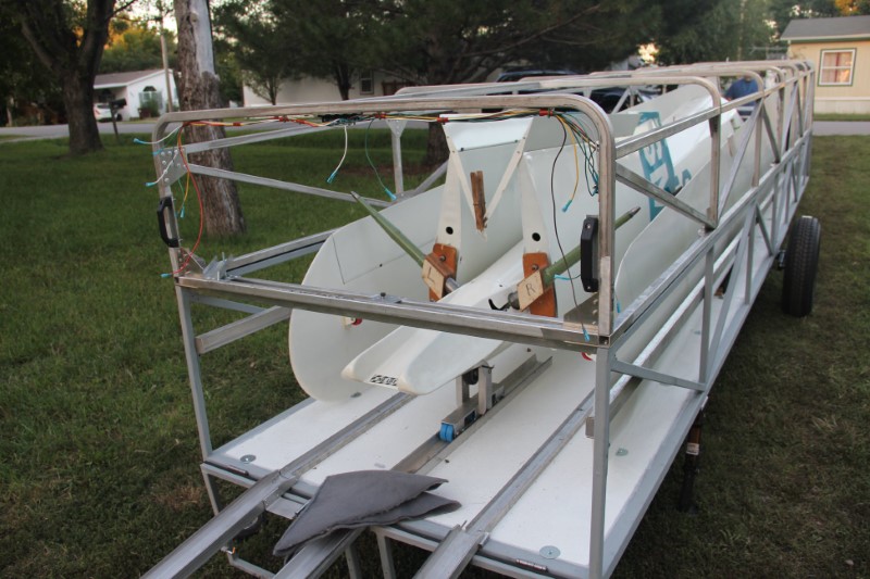
Next, I constructed the wing root dollies. They were inspired by the dollies on a Zuni trailer that is based at our club. The forked portion that accepts the wing root pivots slightly to allow the wing to be swung outwards a bit after clearing the trailer when rigging.
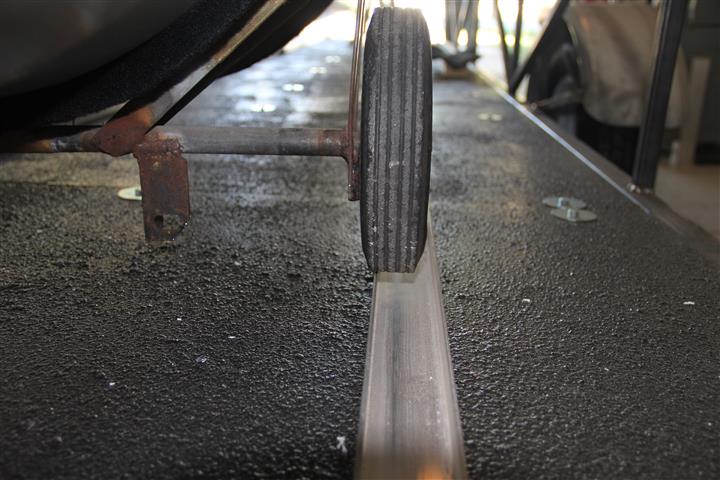
Each dolly rolls the length of the trailer and is captured; by design, it cannot tip out of the track, or roll out of the end of the trailer. Surplus Center has a great selection of wheels, and is where I purchased all of the small wheels for the interior handling parts. The bottom wheels on the dollies happen to be shopping cart wheels.
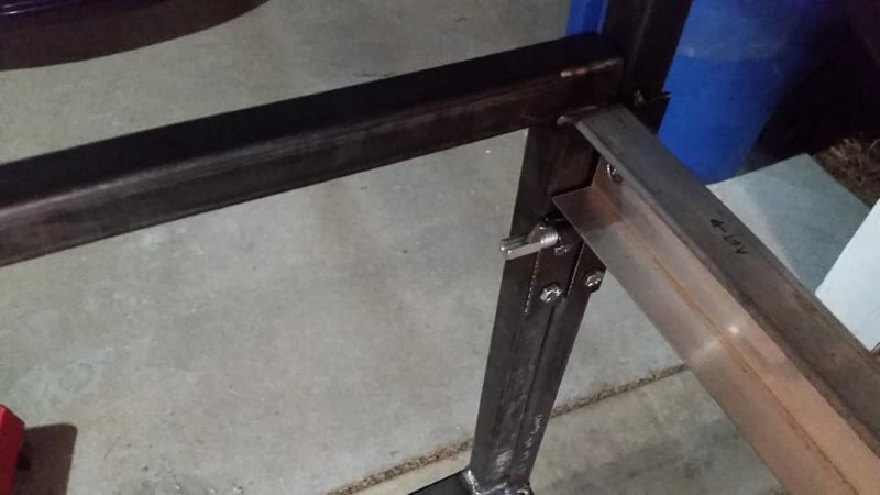
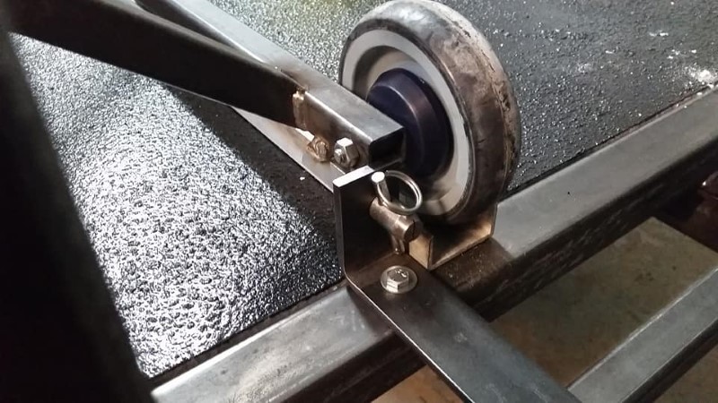
At the front of the trailer, I added this feature to prevent the dolly from moving forward or backwards when the trailer is moved.
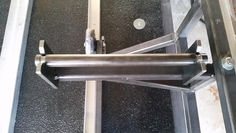
Here is the completed wing dolly, with a closeup of the rod that fits through the spar fitting of the left wing of the SH1. A delrin sleeve was later fitted over the steel rod. This particular interface is copied directly from the glider manufacturer's trailer interface drawing.
I'll also add that I test-fit the wing root dolly parts that interface with the wings prior to finish welding them.
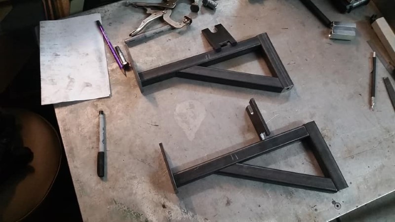
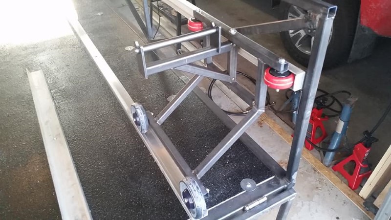
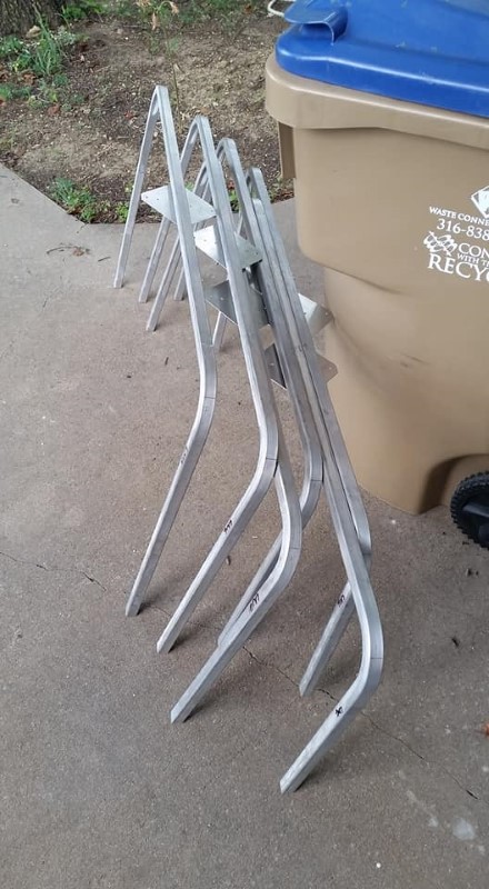
Finally, here are the two completed wing root dollies in position at the front of the trailer.
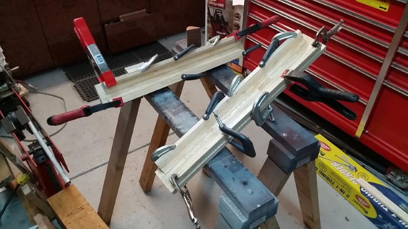
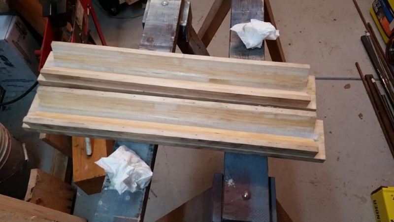
The tip of the wing (actually about 1/3 of the span inboard of the tip) rests in a wooden cradle shaped to fit the leading edge of the wing. This cradle bolts to the floor and is lined with felt to protect the finish on the glider. I cut a series of trapezoidal profiles with the table saw to approximate the desired shape in layers, then epoxied them together.
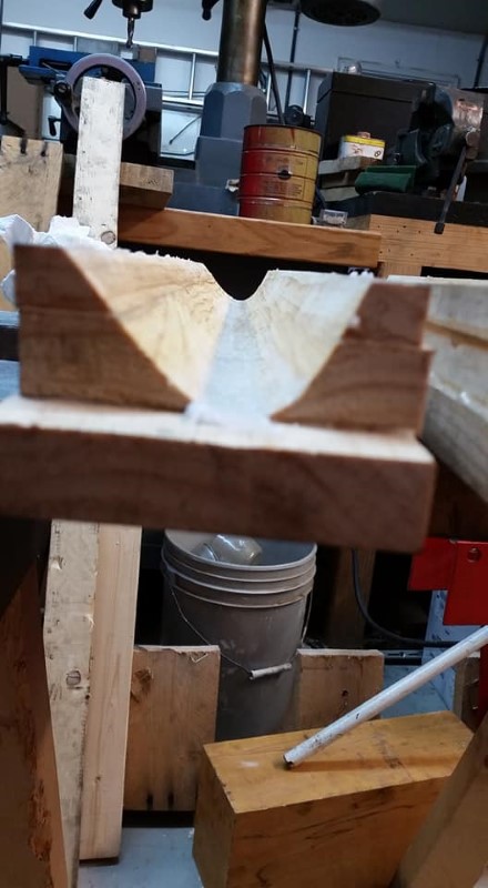
After the epoxy cured, I mixed up more epoxy and micro and spread it into the cradle with an aluminum piece cut to the shape of the wing leading edge profile.
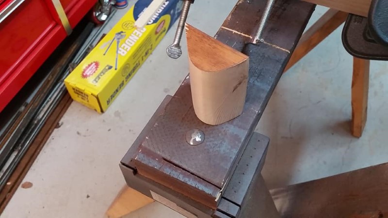
I then cut a sanding block in the shape of the desired profile, and used it to sand the interior of the cradle until it was the proper profile along its entire length.
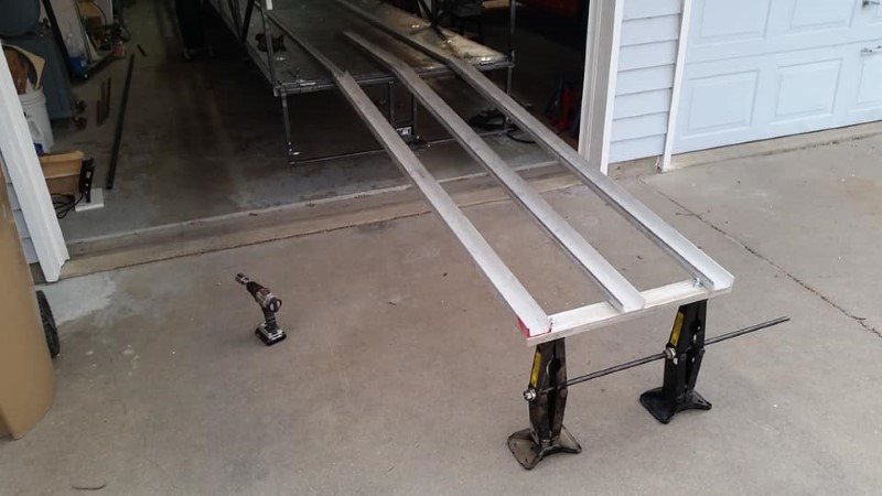
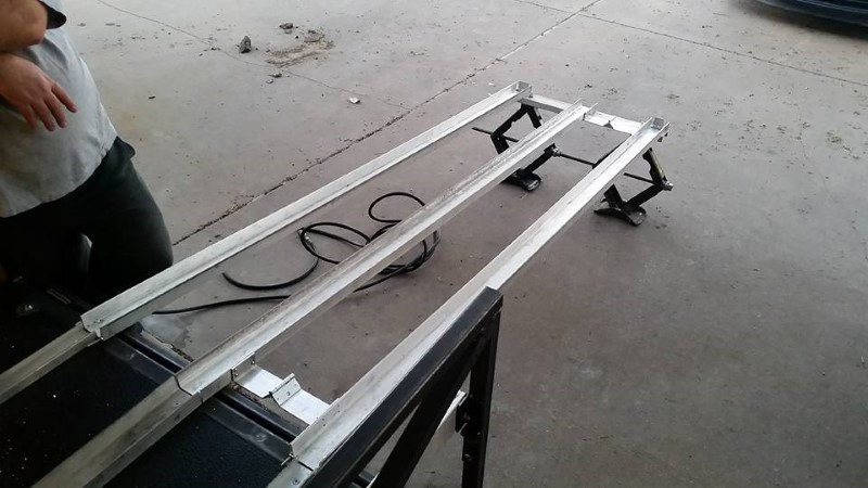
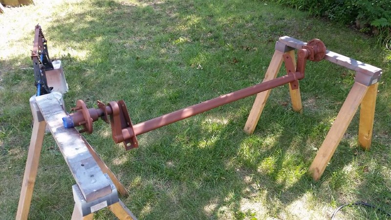
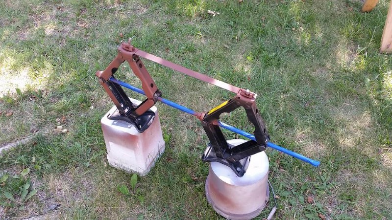
With these tasks completed, the next was to build the folding ramp for the fuselage to roll out on, similar to a Cobra trailer. I found some nice, sturdy 1.5" x 3" aluminum channel sections at The Yard Store, and turned them into a ramp, but first, I had to gang together two car emergency jacks. My Dad spent several years trying to find two identical jacks at auctions. He eventually found two (at the same auction, nonetheless!) that were both the same part number and had the same thread pitch. Since the threaded rod happened to be a standard ACME thread, I purchased a length of threaded rod from Grainger, as well as some ACME thread nuts, and proceeded to remove the existing threaded rod from both jacks, and connected them together with the new one. While I had the jacks disassembled, I added grease fittings, since these are not really intended to be used more than a few times.
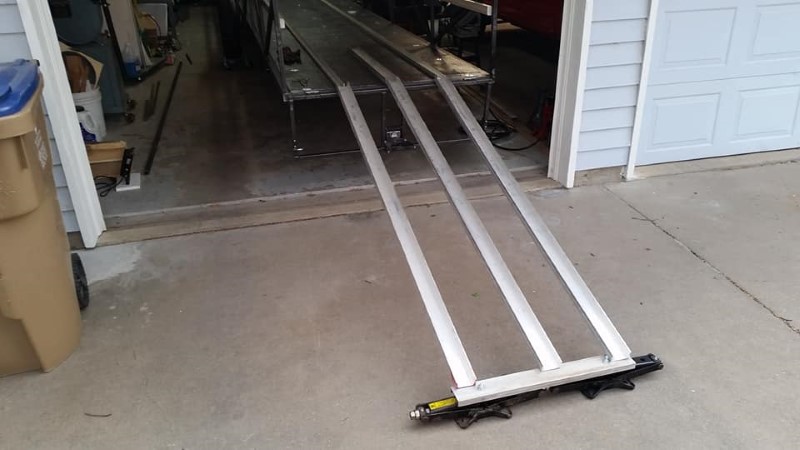
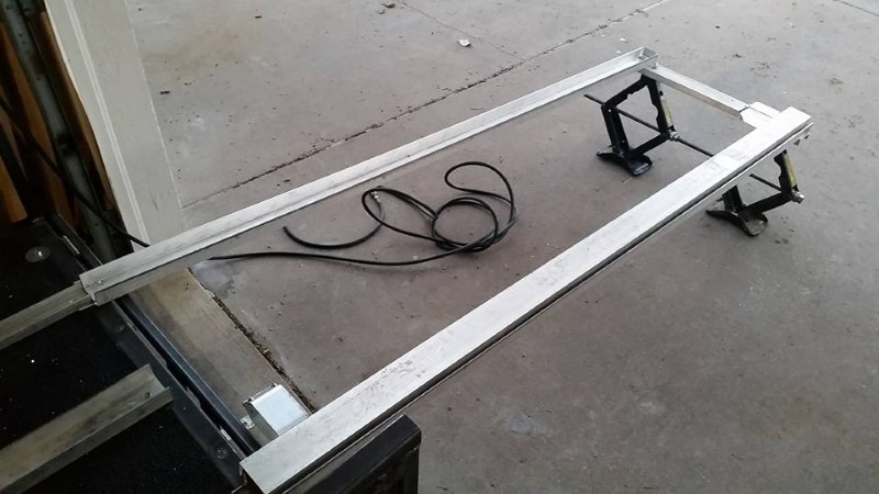
First, I attached a piece of channel across the top of both jacks, then attached the two outer ramps to it. Folded and stored, it fits like this in the trailer:
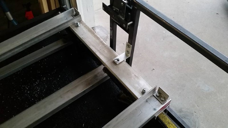
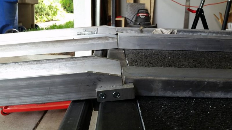
When the ramp is deployed, a bolt threaded into a nylon bushing on the bottom drops into the gap between the trailer and tailgate to restrain it fore and aft. I also bolted a small block of aluminum on the outside of each rail to restrain it laterally when in this position.
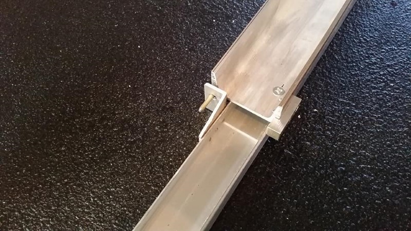
I drilled and tapped a hole in the end of each ramp, and threaded in a long pin. This pin mates with a fitting attached to the fuselage dolly rail on the floor and retains the forward end of the ramp laterally and vertically.
The next two photos show the deployed ramp all the way up and all the way down, respectively.
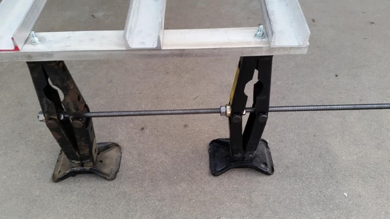
These two photos show the jack/ramp interface and the hinges I made to connect the top of the jacks to the channel that connects the two ramps together.
The center ramp (for the tailwheel) is hinged off of the left side ramp, and folds over onto the left side ramp when the ramp is stowed. A couple of bungee cords make sure it doesn't flop around during transport.
Lastly, the back end of the stowed ramp is restrained in all directions with this angle bracket and pin attached to the tailgate. This, coupled with the forward mounts shown previously, completely constrain the ramp in the trailer when stowed.
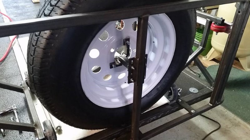
I wanted interior storage for the spare tire. It happens to fit right between the wing roots at the front of the trailer. I made a bracket to bolt it onto the front of the trailer in a location that can be accessed without emptying all of the rigging devices out of the front of the trailer.
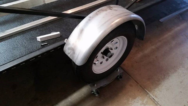
I'll briefly note the fenders here; I had the brilliant idea to mount them to the brake flange on the axle instead of to the side of the trailer to avoid unnecessary penetrations through the side of the trailer, but it didn't work. The mounting brackets cracked in less than 100 miles. As of this writing, I have removed and not yet remounted the fenders to the side of the trailer.
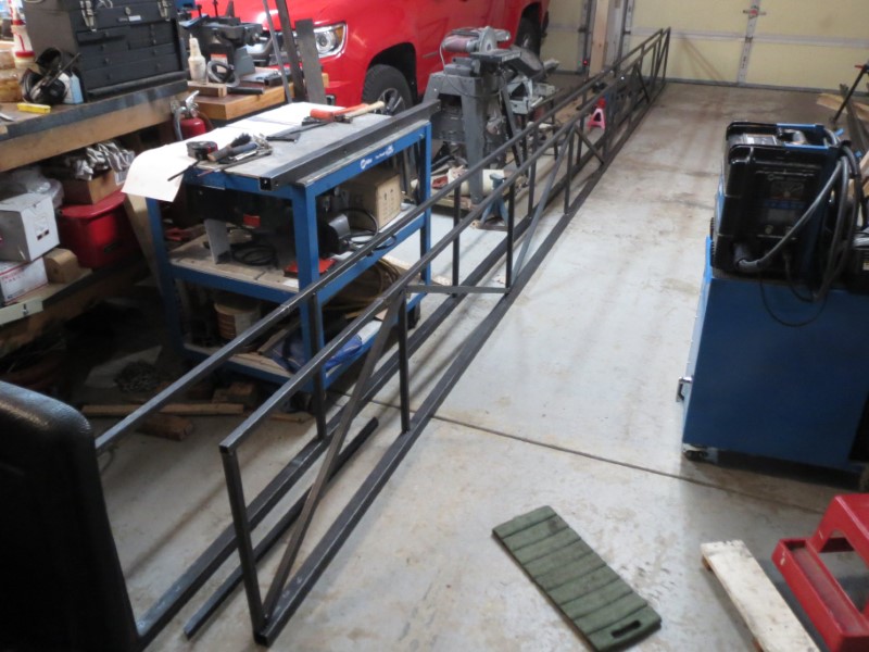
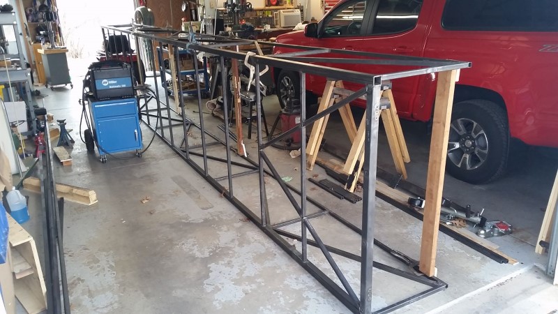
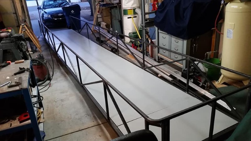
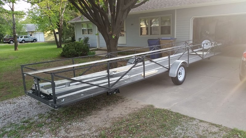
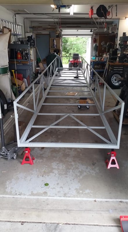
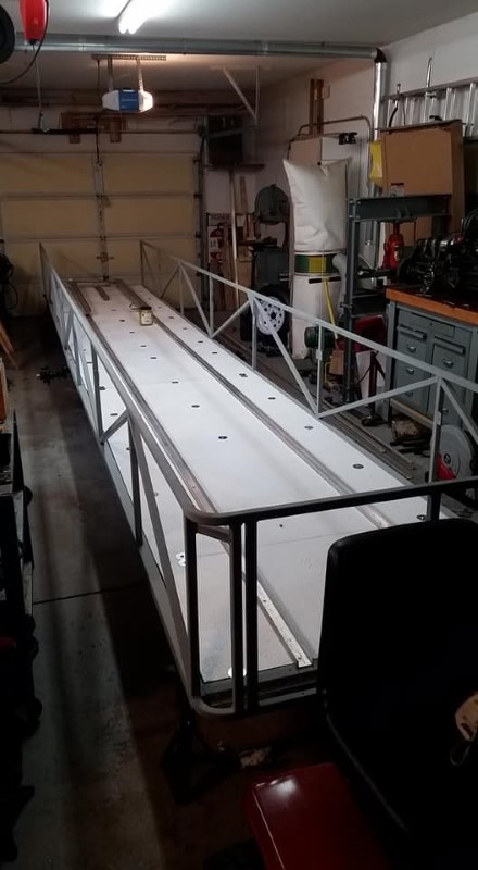
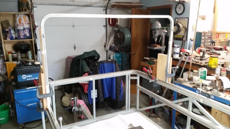
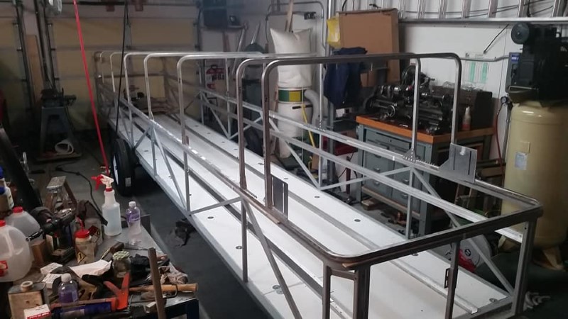
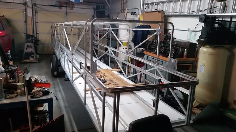
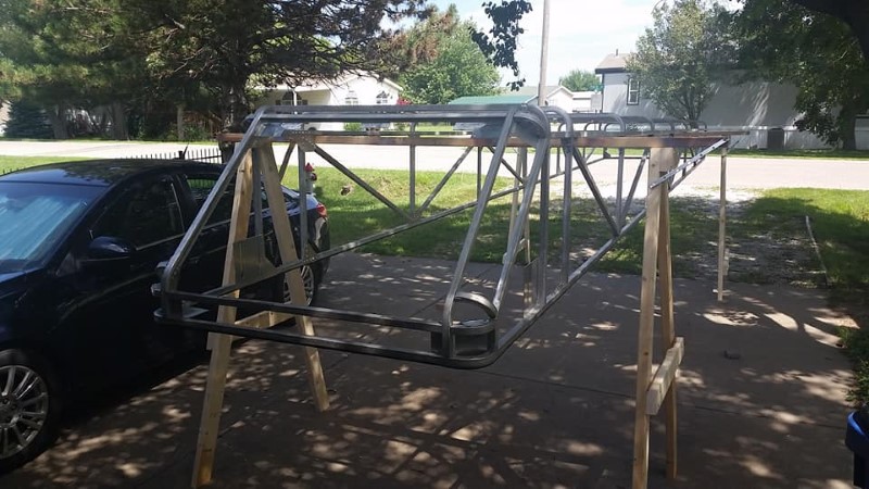
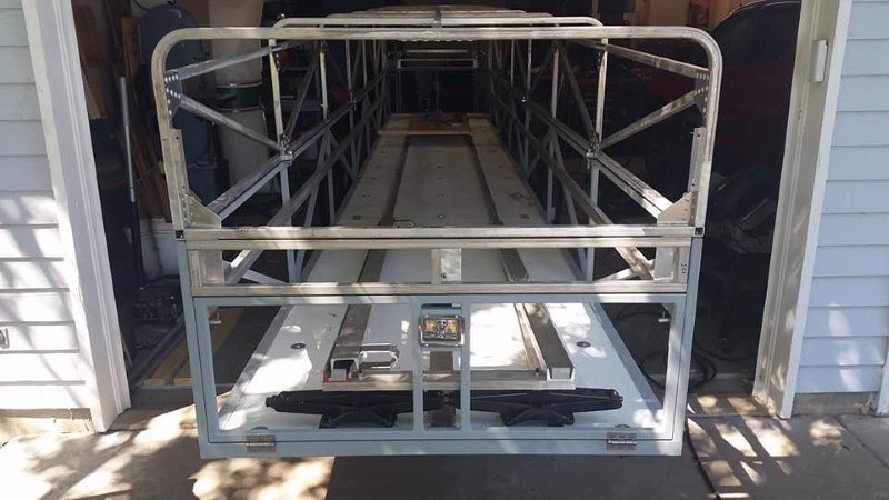
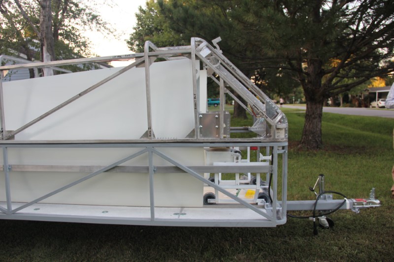
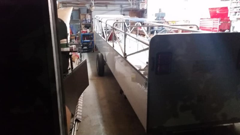
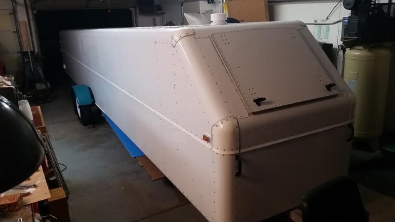
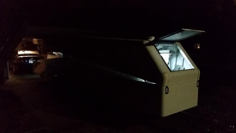
Finally, on May 18, 2018, the lower portion of the trailer was functionally complete and rolled out of the garage for the first time.
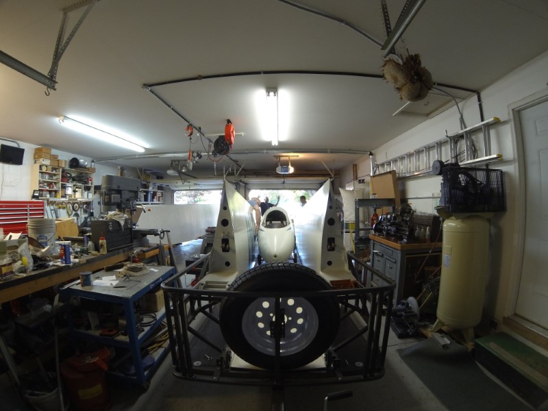
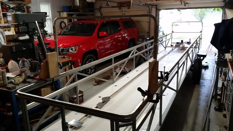
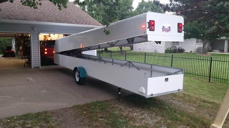
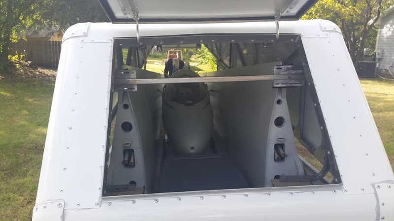
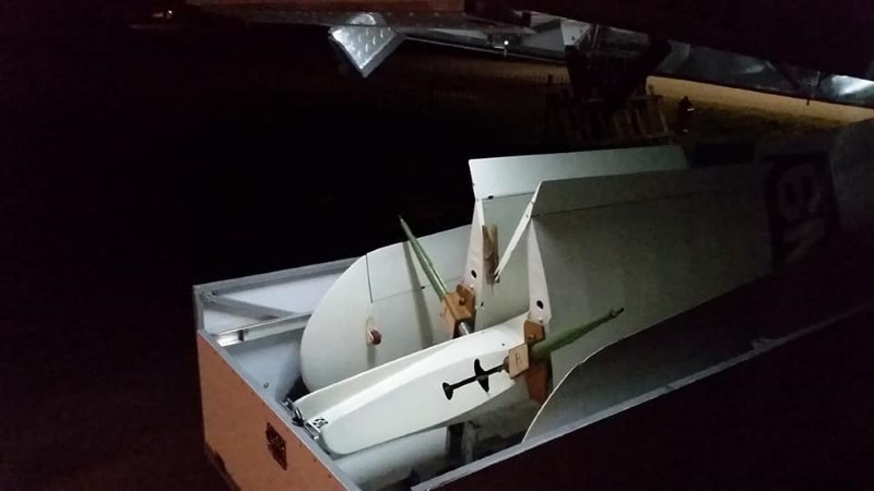
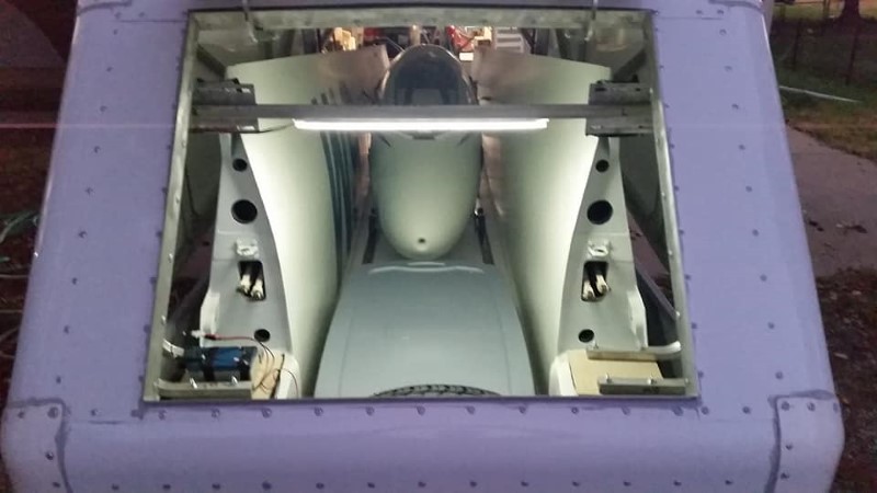
With some help from a couple other glider pilots in my soaring club, we first placed the wings and then the fuselage into the trailer to make sure everything fit properly. Here is a screen grab from a time-lapse video I recorded of the fitting process.
There were only a couple of minor problems that were fairly easy to fix. This was the dumbest one. Somehow, I managed to get the spacing of the rails for the fuselage dolly slightly wrong:
The remedy for this was to make some two-wheel bogeys for each side of the fuselage dolly with more shopping cart wheels. This widened the track slightly and made it fit perfectly.
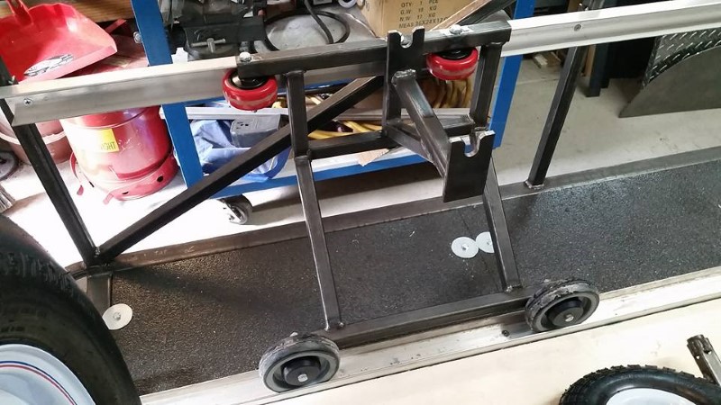
The other issue was that this feature of the wing root happened to line up exactly with one of the upper wheels on the wing root dolly, preventing it from being rotated outwards to clear the fuselage and allow for the insertion of the wing rigger.

This was easily fixed by moving the the aft wheel forward, as shown in the picture below. The wheel that was moved was the red one on the right.
One last minor issue- the ramp ends got VERY close to the fuselage and wings, so I cut the corners off to provide more clearance.
Thanks largely to the hundreds of hours spent designing this trailer before starting construction, these were the only issues I encountered with the fit of the bottom half of the trailer. All of that work up front really paid off.
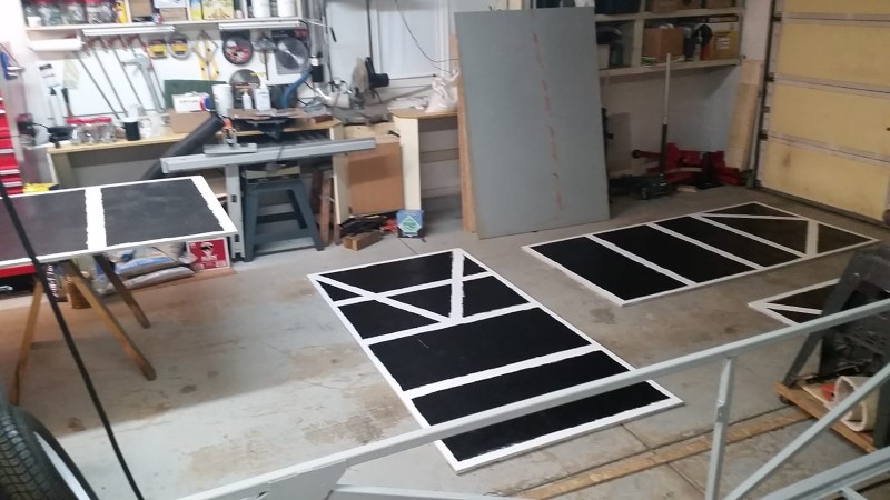
Before building the clamshell top for the trailer, I wanted to get the bottom half of the trailer completely finished and ready to be skinned with sheetmetal so that it could be skinned at the same time as the top. First, the floors- It was decided when we were trying to put the glider into the trailer during the test-fitting that it was going to be really hard to see inside the trailer with the black floor, so I painted over the rubberized coating with some Kilz paint/primer combo I found at Menards that is supposed to stick to just about anything. Since there is no foot traffic on it, and it is only exposed to the sun when the trailer is open, it should be fine. I later learned that auto paint stores sell colored undercoating, including white. If I were to do it again, I would have done that instead.
I also painted the underside of the floor panels with the same rubberized coating I described earlier for the top. I am a bit concerned about what will happen if the tow vehicle throws a rock and it hits the underside of the floor, but so far this hasn't happened. 2020 will be a good test, with trips to Little Rock for the SSA convention and Elmira, New York for IVSM.
I didn't want the rough rubberized coating where the structure supports it, so I masked off those areas and did not put the undercoating on them. I instead applied some single-stage polyurethane primer and paint with a roller. This was the only product I could find that I was reasonably certain was compatible with the undercoating that did not cost a fortune.
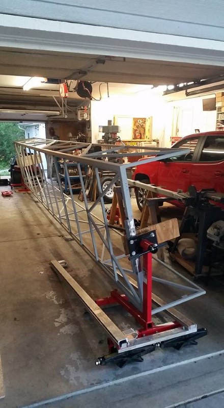
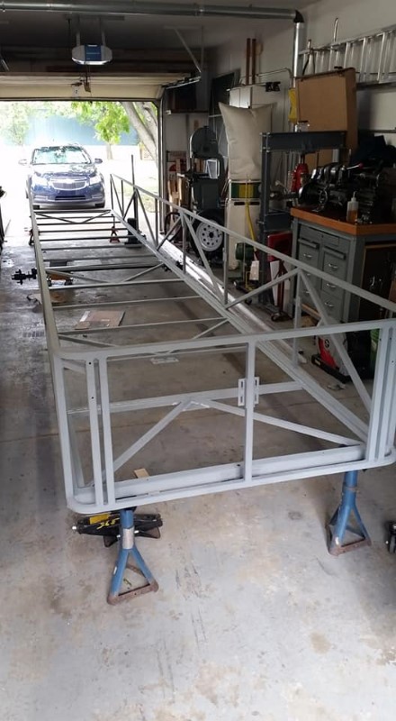
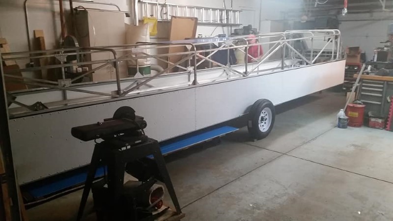
In preparation for painting the trailer, I bought a couple of engine stands from Harbor Freight and used them to make a rotisserie for the trailer so I could rotate it to any angle for cleaning and painting.
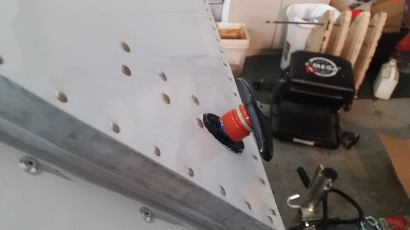
Prior to painting the trailer, all of the mill scale and protective oil needed to be removed from the tubing. In hindsight, this should have been done when all of the tubes were bare, before I cut and welded them together. This made the process a bit more difficult and time-consuming. After much frustration and experimentation, I finally found the easiest way to get the tubing down to bare metal- Black+Decker 4.5" Power Strip Disks, part number 70-6P4SM. They are sold at Walmart and very, very rapidly remove all surface contamination. After spending many hours scrubbing the whole trailer with that, I wiped it down with denatured alcohol, and then used RM-801 metal conditioner to prep the trailer frame for best paint adhesion. I bought some of this product years ago for a project, and I use it on all ferrous metal items in my various projects before painting them. It etches the metal and will also remove light flash rust.
I spent a lot of time, probably months, deciding how to paint the trailer frame and what to paint it with. Modern catalyzed polyurethane paint is great stuff, but it is also pretty expensive and not very "city living" friendly to spray. I wasn't looking forward to turning half my garage into a spray paint booth and having to deal with how to get fresh air in and keep the overspray from painting all of the cars in the neighborhood. Someone in our club mentioned a product to me in passing, and after some exhaustive research, I decided there probably isn't a better product for this particular application:
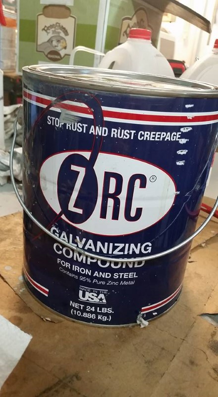
Internet research suggests this stuff is nearly as good as hot-dip galvanizing. I couldn't find ANY bad reviews, and this stuff has been around since the beginning of time. People have used it on floating docks and other submerged structure, and it works. It can be applied with a brush, which makes touchup extremely easy when the inevitable "I missed a spot!" discovery occurs. I also didn't have to mask off the garage, wear a bunch of protective equipment to breathe, or deal with overspray. A gallon of this stuff costs about $150. It was fun to get people to heft the can and watch their reaction, as it weighs 24 lbs full. Initial stirring was extremely difficult, but once I got it mixed up, applying it was easy. The only other downside is the weight it added to the trailer, but after about a year and a half outside, it still looks like new.
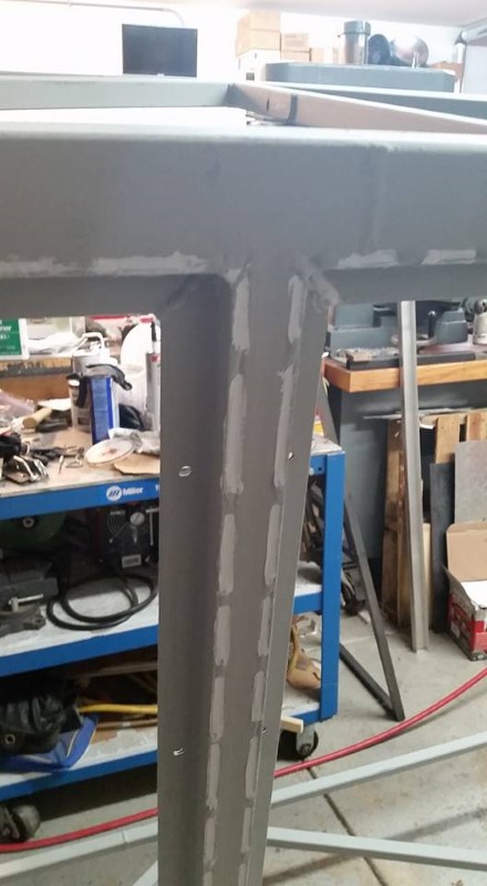
The rotisserie made it pretty easy to get at all of the corners and joints. After putting it down on jackstands, I just had to do the area that was blocked by the mounting points.
I bought a brand-new custom width axle (more details on that to follow) that I sadly had to repaint prior to installation, as from the factory there was pretty obvious paint over runs in several areas. I think they stored the raw materials outside prior to painting and did not clean them properly. So, I stripped it and reprimed and painted it with Rustoleum red oxide primer and gloss black.
I also did a bit of touchup on some rusty areas on the ramp jacks.
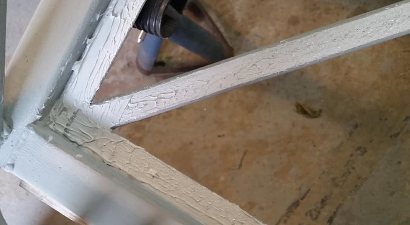
For my day job, I am a structural analysis engineer with large commercial aircraft experience, and I have extended some of the same philosophies used in commercial aircraft to protecting my trailer from the elements. Every gap and crevice where water could get was filled with sealant to prevent water intrusion.
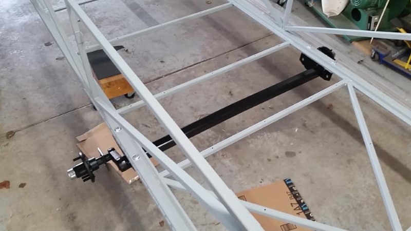
Here is a detail view of the sealant applied in between the stitch welds at the axle reinforcement. I also put sealant between the mating surfaces of the axle flange and trailer frame, fillet sealed around the joint after the bolts were tight, and also put sealant under the washers and bolt/nut heads. I have seen a couple of trailers with structural failures due to rust where the axle attaches, and all of this should prevent that.
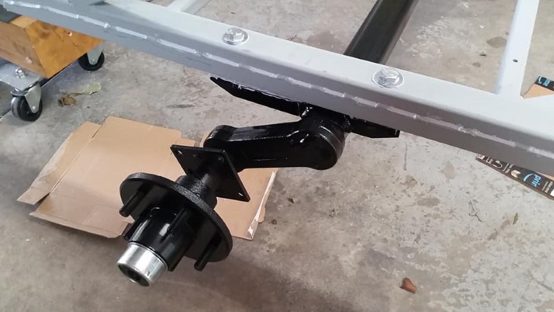
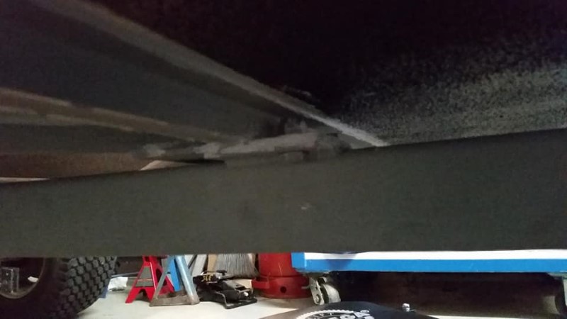
Here is the completed axle installation. It is a custom-width 2000 lb Dexter Torsion Axle, ordered through a local trailer equipment retailer (Redneck Trailer). It is available in several different axle link start angles. I picked one that gives me over a foot of ground clearance and designed the rest of the trailer around that. My previous trailer was very low to the ground, and I had to be extremely careful picking routes out of my neighborhood, as one of them had too steep of a ramp, and the back of the trailer would drag on the ground. In the hopefully unlikely event this occurs on the new trailer, I have fitted an aluminum skid on the back edge of the trailer. I chose the width as to keep the overall track of the trailer fairly narrow. I did a bit of math and calculated the speed at which the trailer overturns in a tight radius turn, using the weight and CG data from the Solidworks model and some Google Earth measurements of the radii of the worst cloverleaf interchanges I have experienced. My conclusion with that is I will be scared to death driving at a speed lower than the trailer would actually turn over on a tight curve.
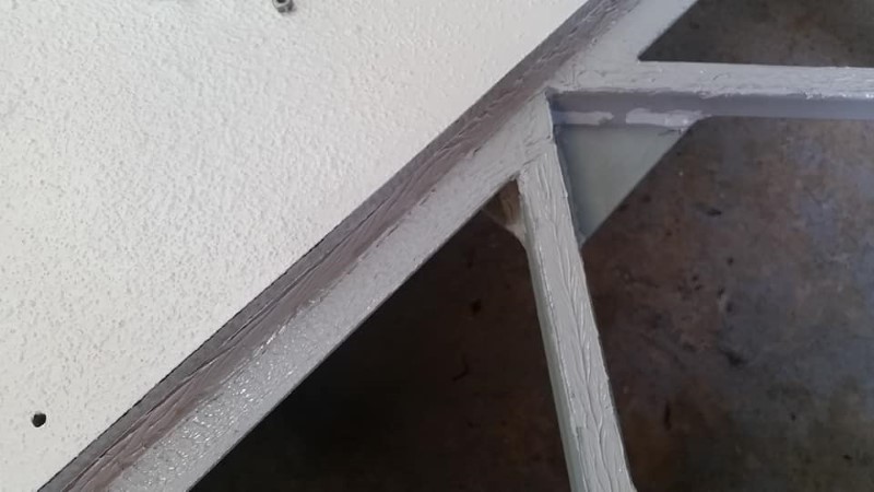
Here is the completed, painted, and sealed frame:
While not exposed to as much weather as the trailer frame, I painted the tailgate and some other misc. parts with the zinc paint as well, since I had enough. The gallon was more than plenty for this project.
Before installing the floor panels, I applied sealant to all of the lateral supports to prevent water from being trapped between the structure and floor. The sealant used for anything and everything that needed sealing on the trailer is Loc-tite UR7001 Urethane Sealant. I chose this for its compatibility with all of the materials I used, as well as the 24-hour cure time (this was helpful for installing skins). Around 10-12 10 oz tubes were required to seal everything on the trailer.
After the floors were installed, I tooled the sealant, making sure there was a nice, smooth fillet seal at every interface. At this point, it is just about impossible for water to get into either the interior of the trailer, or inside of the steel tube structure.
Floor permanently installed:
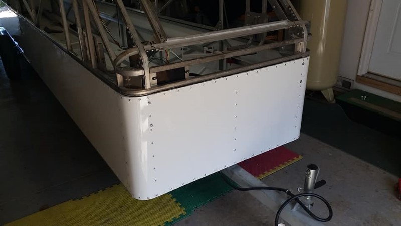
To fill in the rounded front, I riveted on a piece of scrap diamond plate. I applied sealant between the mating surfaces, and dipped all of the rivets in sealant before installing them.
At this point, it's now roughly August 2018, and I'm quite a bit behind my scheduled completion date. The top turned out to be a very labor-intensive process. I had intended to MIG weld the aluminum tubing structure together with a spoolgun, but I could not get welds on the tubing that inspired any confidence, so I designed a bunch of sheet aluminum gussets in various thicknesses from 0.050 to 0.071" thick, and attached them to the tubing with structural blind rivets from McMaster-Carr. However, the first step was to bend and trim all of the "hoops" forming shape of the trailer along its length.
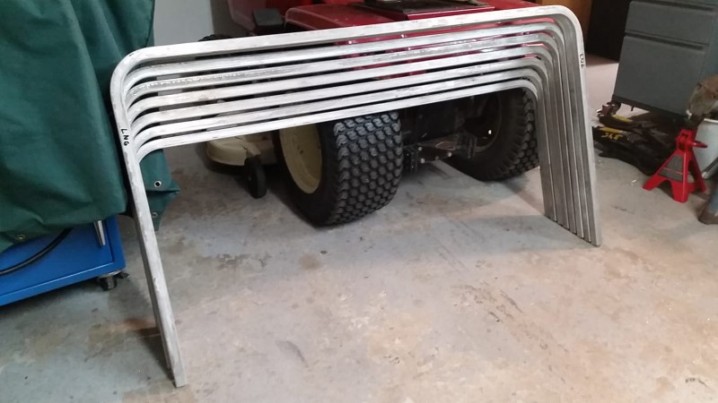
I used the same bending dies as for the front pieces of the bottom half of the trailer, but some creativity was required to get the bends on a continuous piece, and then trim the completed frames to a precise length:
I made up most of the gussets before starting assembly. I only needed about six different types, plus a few special ones to fasten together most of the framework for the top.
I started by clecoing the required gusset to the top centerline of each frame.
Before I could fasten all of the frames to the base of the clamshell, I had to splice the front piece to the 24' long tubes that made up the sides. Complicating this was the requirement for a flat bottom for a seal to be fastened to later on. I ended up buying some long countersunk aircraft bolts, and made a delrin block that fit tightly inside of the tubes to make the splice.
I started with the aft-most frame. I clamped it in position with a special pair of wooden fixtures (not shown) to hold it canted 2 degrees off of perpendicular towards the back of the trailer. This was done to make layout and fastening of the skins easier, as all frames would be parallel to each other, despite the clamshell top tapering in height from front to back.
Next, I clamped the forwardmost frame in position, and then riveted both frames on.
Both frames before riveting.
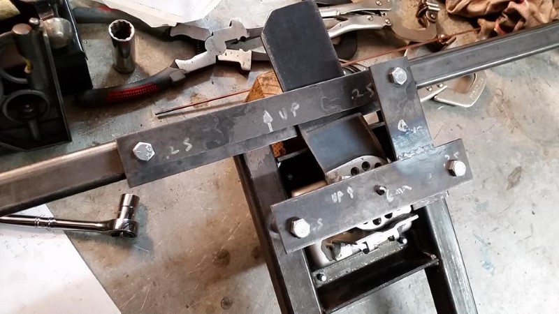
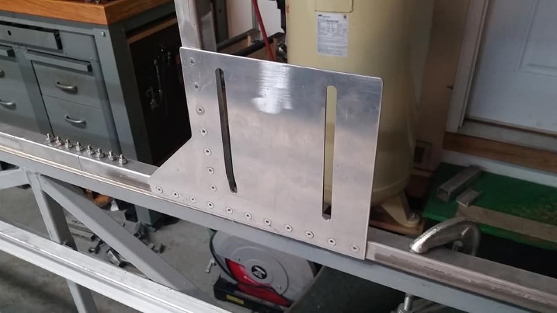
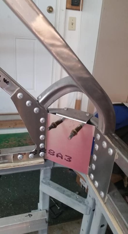
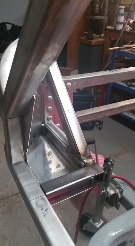
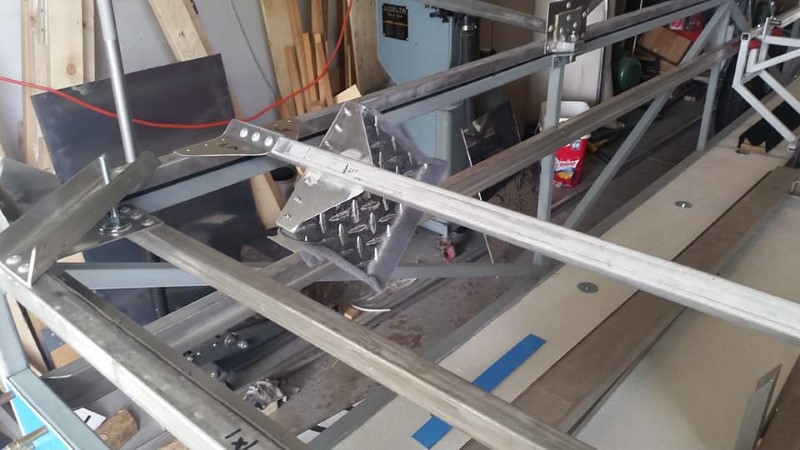
The forward frame gusset doubles as an adjustable mount for the device that captures the wing spar stubs in the trailer. Pay no attention to the lower half of the aft slot- I apparently didn't have the parts clamped tightly enough in the mill, and they moved. Thankfully, I ended up not needing the lower portion of the adjustment range. I used countersunk rivets to attach it, as the mating half of the wing root clamp needed to be able to slide over it. The variety of rivets used to hold the top together will be discussed further down.
Here is a more detailed view of the aft-most frame attachment. Notice the glue around the edges- I applied some Loctite PL Premium Construction adhesive to the mating parts after first scuffing off the oxide layer with a scotchbrite wheel and then cleaning with Isopropyl alcohol. Probably not necessary, but it does provide some additional strength to the joint.
To fill in the remainder of the rest of the frames, I pulled two strings taut between the forward and aft frames at the radius tangency of the bent corners. This would help me position the frames so that the top of the trailer would be flat and properly aligned. Working from back to front, I installed the remainder of the frames. This was done so that all of the skins would be parallel and remain their as-manufactured 48" widths.
I then put in the rest of the frames, starting at the back. The spacing between each one was held to a precise value, and all of the tolerance along the length of the trailer was washed out between the forwardmost frame and the one behind it, which are closer together than 48".
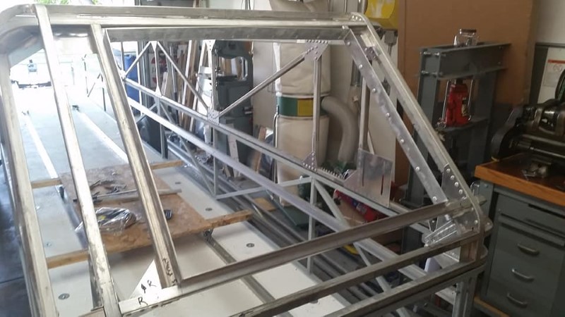
After all of the frames were set, I started filling in the longitudinal members in between the frames.
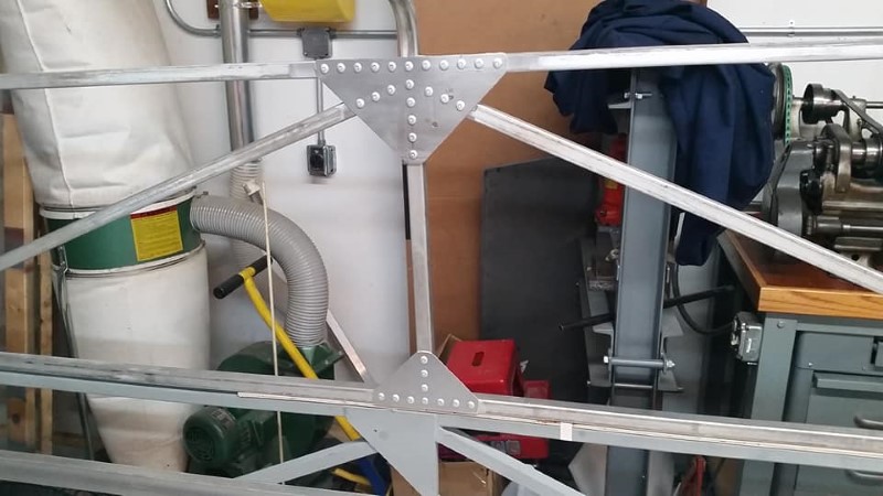
Once all of the longitudinal members were installed (with the exception of the forwardmost bay between frames), I installed all of the diagonal braces. The photo below shows a closeup of the gusset where one of the gas springs that holds up the top of the trailer attaches. I used 1/8" thick 6061 aluminum for the gusset, and twenty-two 1/4" structural blind rivets to attach each of the gas spring support gussets. The number of rivets is far more than would have been required given the loads, but spreading the load out over a greater area should keep this area of the trailer from developing cracks in my lifetime.
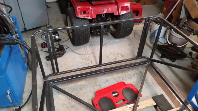
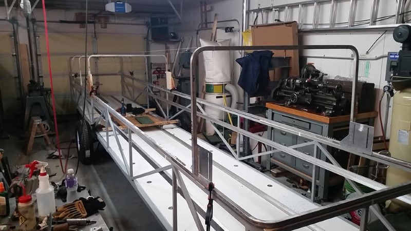
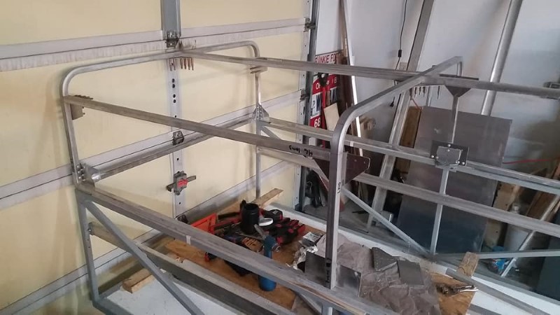
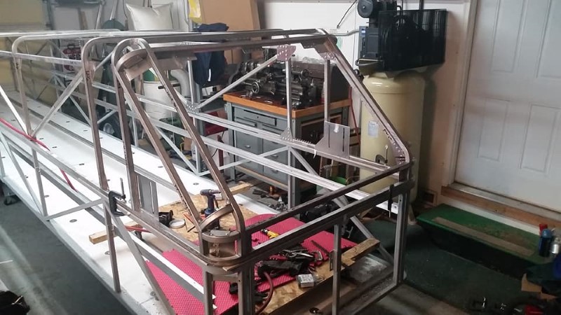
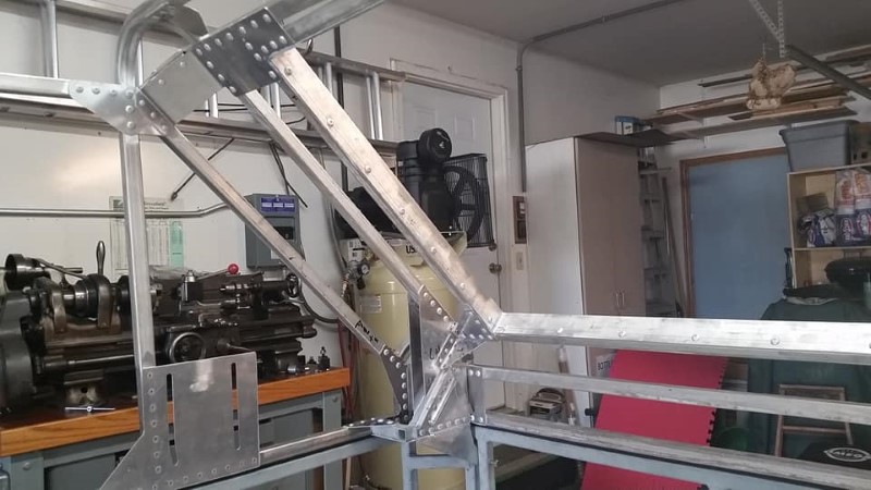
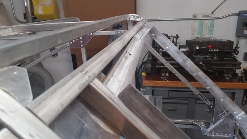
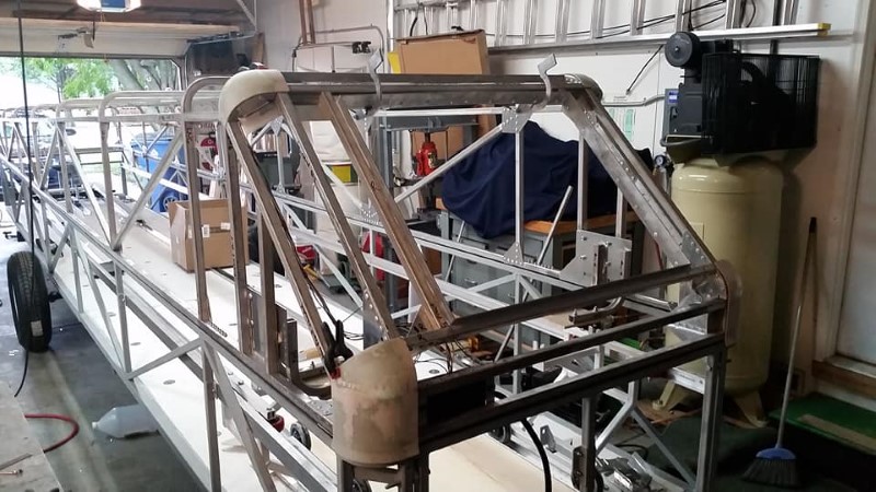
At this stage, the trailer looks like this:
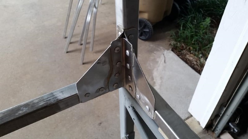
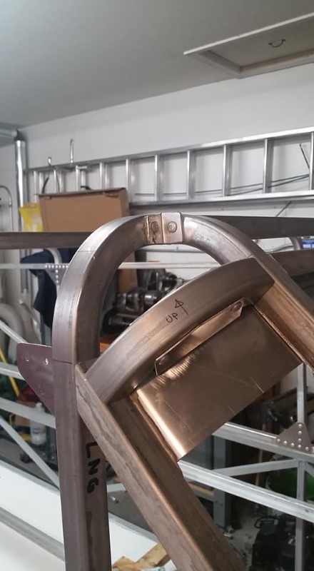
One of our club members insisted that I design the trailer with nicely rounded corners at the front to match the bottom of the trailer. This ended up being very challenging, and it also required a lot of little pieces to fill in all of the structure around the corners. Here are examples of the lower and upper corners of the top of the trailer.
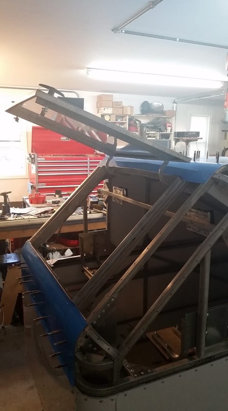
At this point, the overall shape of the top of the trailer is complete, but more structure is needed to attach the front hatch and the hinges for the clamshell top.
Prior to fabricating and installing the clamshell hinge fittings, I removed the top from the trailer so that a rubber seal could be installed onto the bottom surface of the trailer top. I actually ended up doing this twice- my first attempt, a 1/4x3/4" flat seal, was too stiff and did not compress enough into the slight warped regions of the mating surface of the bottom half of the trailer. I ended up removing that and replacing it with a bulb seal, which has worked much better.
After the installation of the seal, I set the top back on the bottom of the trailer, and then clamped it down in a few locations to keep it from moving while I installed the clamshell hinges.
Since I didn't design any folding braces into the trailer similar to what Cobra, Comet, etc. used, any side loads on the top of the trailer with it open have to be reacted out at the hinges. This results in a design load in the hinges of about 1000 lbs. I did some stress analysis on the clamshell hinge fittings and their attachment to the top of the trailer, and determined that some steel tubing would be necessary to get the load out into the surrounding aluminum structure without causing any issues.
I used a lot of gussets to box in the fittings to the structure to make sure the load would be spread out over a wide area. This photo was taken during the initial test fitting of the steel tube weldments to which the hinges are attached. Prior to installation, I painted the steel hinge fittings with the ZLC paint used on the bottom of the trailer.
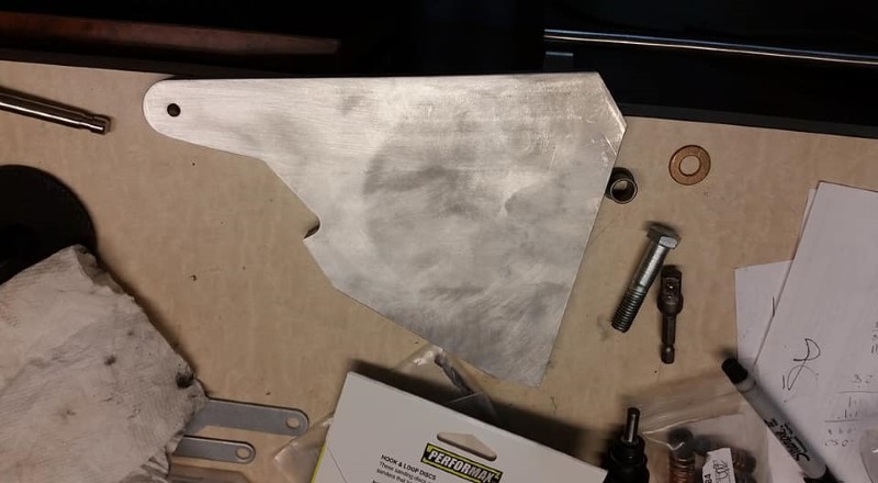
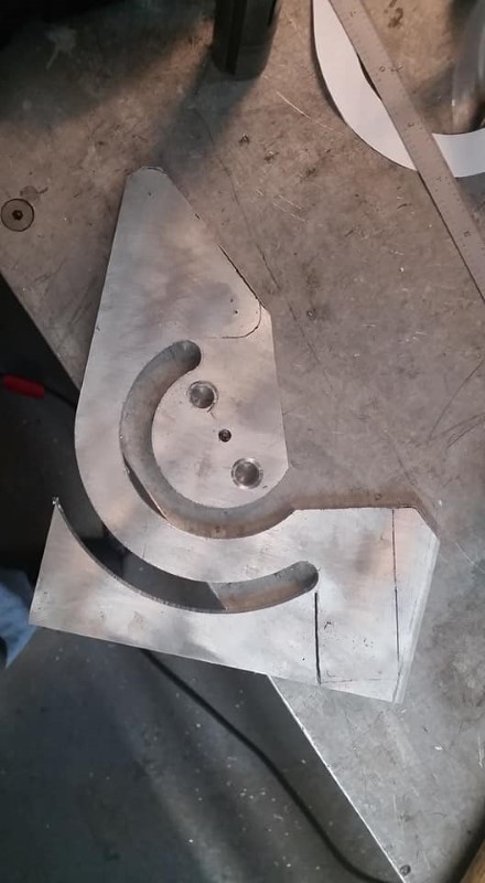
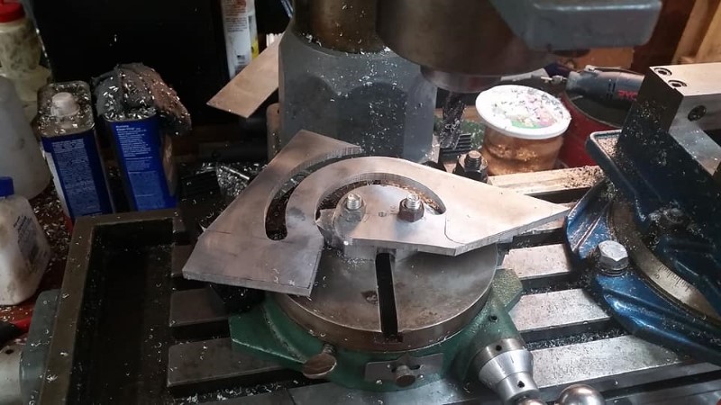
The images below show the progression of the hinge fittings, from block of aluminum to near-finished part. I drilled holes at all of the "corners" of the part to reduce stress concentrations. I did a bunch of rough cutting on the band saw, and then some finish machining with the mill.
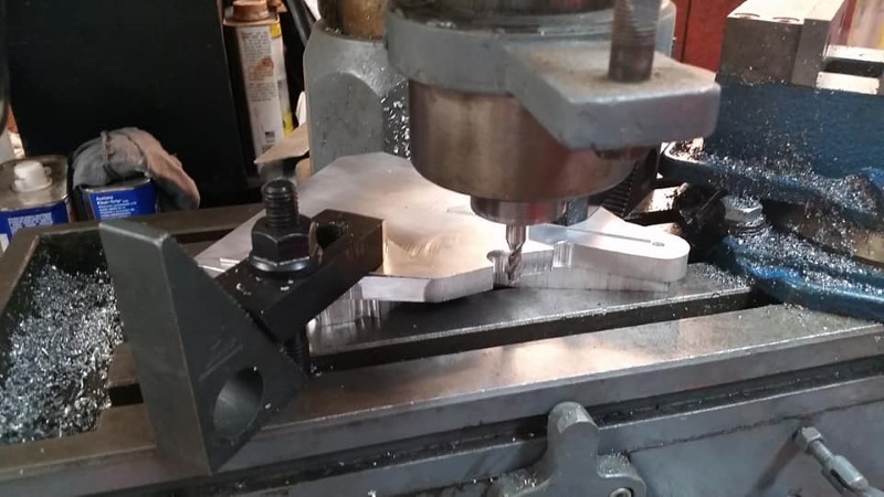
This is probably overkill, but I did it anyway- I installed a bronze bushing into the lug on each hinge fitting, even though these probably won't wear out in my lifetime.

Here, the hinge is clamped in position, and the various gussets that fastener the hinge weldments to the rest of the top are being installed.
The last step prior to riveting on the hinge fittings was to machine down the thickness of the fittings in the area of the rivets. This was to keep the total stackup for the riveted joint lower, as the full plate thickness was not required to develop the full shear strength of the rivets in the joint.
This photo shows the completed hinge installation, as well as the overall complexity of the front portion of the top of the trailer.
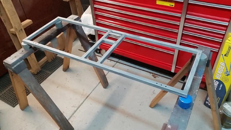
With all of the structure at the front of the trailer complete, the next step was to frame in the area around the front hatch. This was another weak spot I had noticed on both factory and homebuilt trailers. If care is not taken in the design, it leaks. To combat this problem on my design, I made a frame that projected about 1" above the front surface of the trailer, so that water running off of it would be forced to drain around the hatch opening. I put a bit of a crown on the top of the opening to prevent water from pooling above the door opening, as shown in the photo below.
This photo shows the entire hatch and framework. The frame had sealant applied to both mating surfaces before installing to ensure water could not get between the raised portion of the frame and the structure of the opening and leak into the trailer. I also made the hatch very large to ease the extraction of rigging equipment, the spare tire, etc.
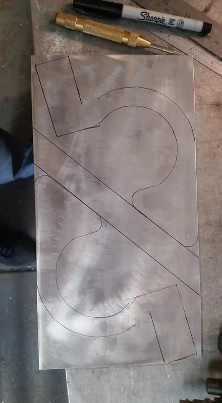
I had two other requirements for the hatch: The hinges and gas springs need to be contained entirely inside the trailer to eliminate another point of leakage, and the hatch must not open by itself when the latches are undone. This is to prevent a forgotten latch from causing damage to the trailer if it is towed without the latches closed. To do this, I made some somewhat complex gooseneck hinges on the mill, and positioned the gas springs on them such that they go over center when the hatch is partially open, which holds the hatch closed. Modeling the trailer in Solidworks made the hinge design easy; I could tweak the sizing of the hinge and position of the gas spring to make sure that it would fully open the hatch without parts interfering, and also over-center the hatch to keep it closed. These worked right on the first try. The next few images shows how I cut the hinge fittings out of a piece of 1/4" aluminum plate:
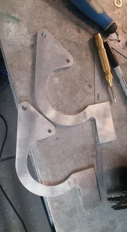
This photo shows the hinge fittings installed in the trailer, without the hatch or gas springs fitted.
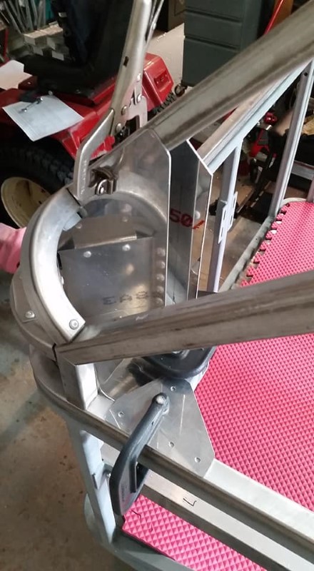
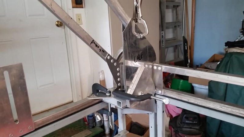
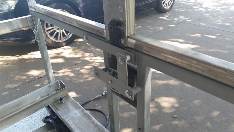
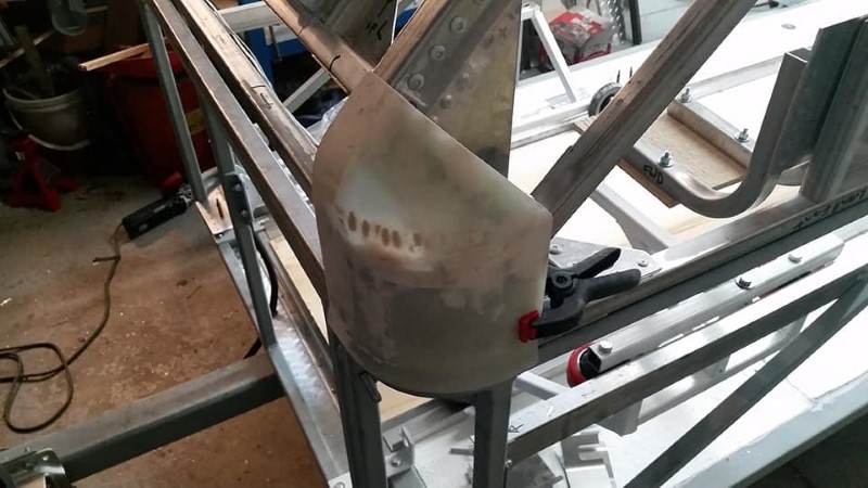
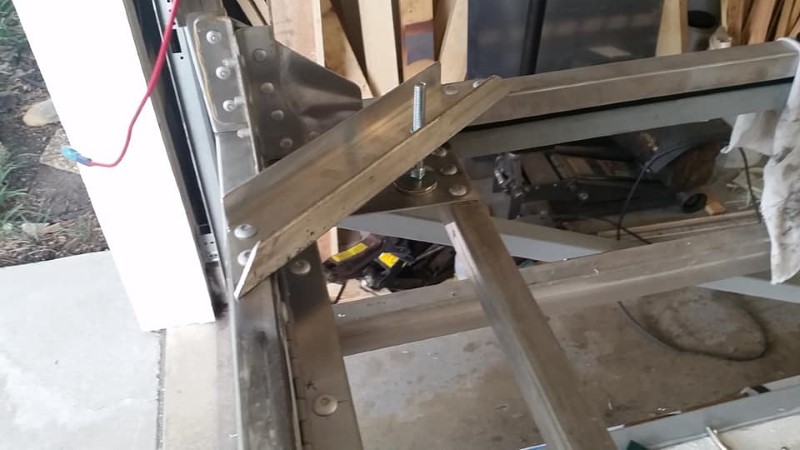
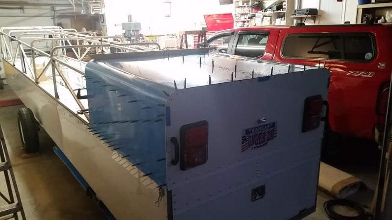
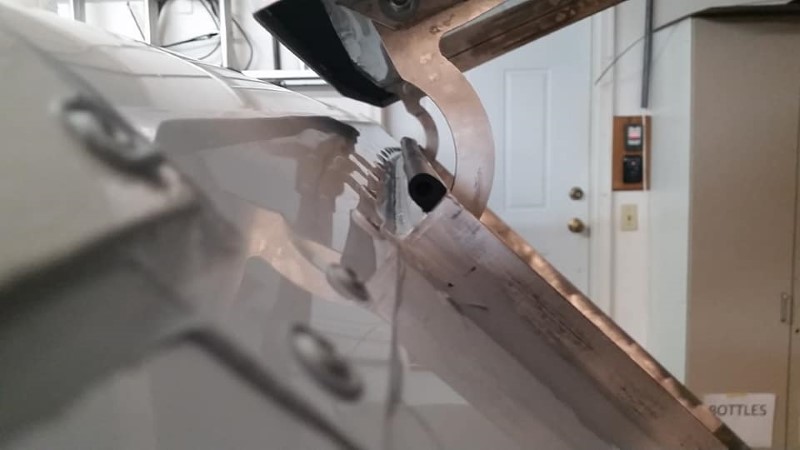
Next, I turned my attention to the clamshell latch at the rear of the trailer. Since I was not able to make the tailgate the full height of the bottom half of the trailer, the top has to stick down at the back. However, this feature would not clear the wing roots without making the bottom 6" of the back of the trailer fold out of the way.
At this point, I cut the slot in the swinging latch plate to catch the shoulder bolt on the top of the trailer.
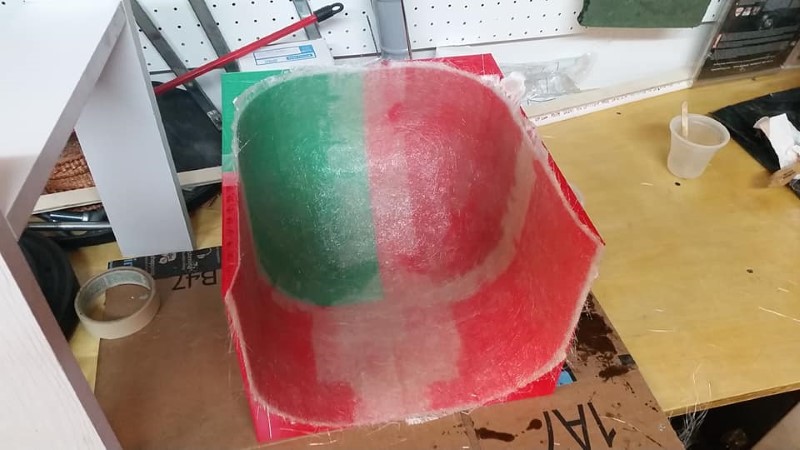
I had put this task off long enough, but now I had to figure it out before proceeding any further, as the trailer was nearly ready to be skinned at this point. The rounded front of the trailer required four corners with compound contour, so they could not be skinned with aluminum. I had settled on making fiberglass corners, but I had no idea how I was going to make them until a coworker mentioned in passing one day that he had just bought a 3D printer. So, I bought him some filament and put him to work printing a female mold that would allow me to lay up all four corners in one shot, and then cut them apart after curing. Due to the printer size limitations, I had to split the mold into four parts and then assemble them together. Here is the assembled mold:
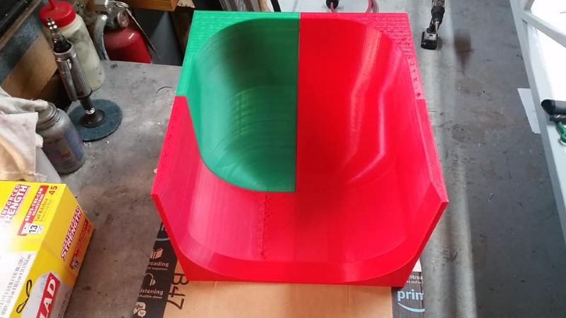
I taped the seams of the mold with packing tape (wouldn't do it again, given the choice) and then sprayed the whole thing with mold release. I first laid in one ply of 1 oz fiberglass cloth, with the hope that it would limit the amount of finish and sanding work, and then several layers of chopped fiber until I reached a thickness of around 0.1". Once again, West System epoxy was used as the matrix for this part.
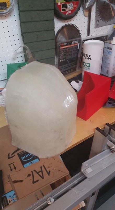
I was able to extract the part from the mold without too much difficulty. I did crack the mold in a few places, but it could still be used again if needed, should I damage one of the corners and need to replace it.
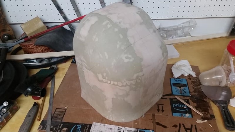
I then went through several rounds of filling and sanding with West System epoxy and 410 Micro filler to fill in all of the pinholes and voids.
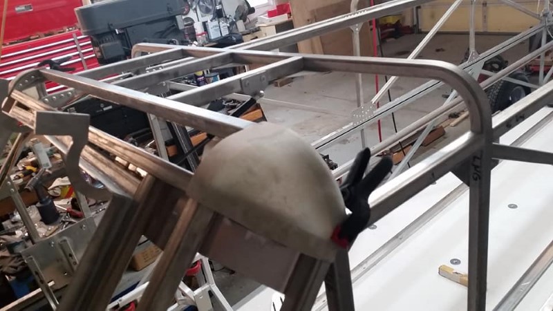
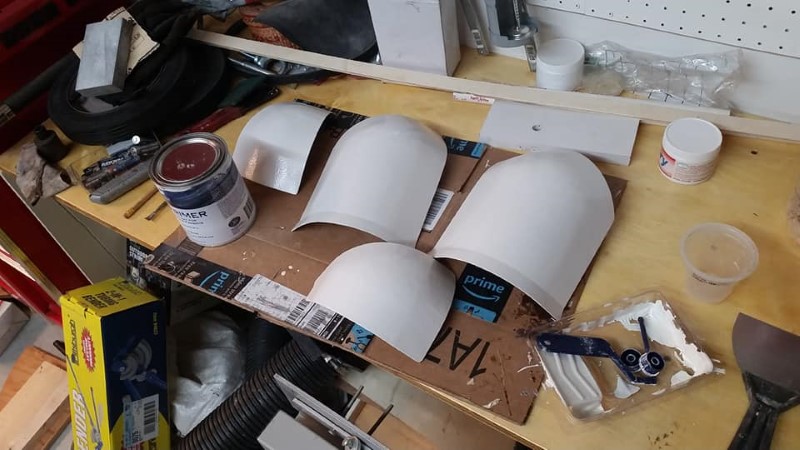
Once I was satisfied with the surface finish, I cut the four corner pieces out, and then started fitting them on the trailer frame, and trimming the edges so that they would fit properly. The mold worked great- all four corners were a PERFECT fit.
The last step with the corners was to prime and paint them. I used the same single-stage polyurethane paint I used on a portion of the underside of the floor. I later discovered when assembling the trailer that this white is not as brilliant white as I thought, but it still performs the function of protecting the epoxy from the sun.
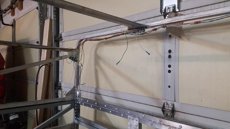
One last task before attaching the skins: wiring. It is much easier to wire the trailer without having to crawl through it after it is done, so I did all of that before skinning it. I bought a 7-pin connector pigtail on Amazon, as well as a junction box. I mounted the junction box near the front of the trailer where it would be readily accessible from the hatch, in the event something needs troubleshooting.
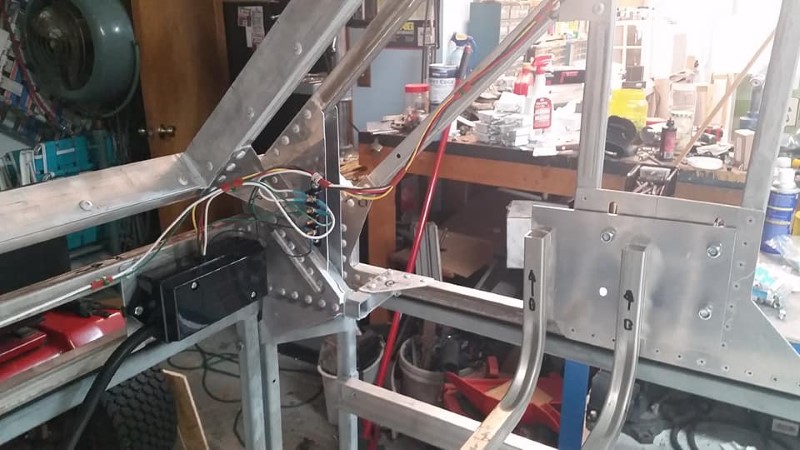
Most of the wiring ended up going all the way to the back of the trailer, as there are taillights, running lights, and provisions for interior lighting at the back. For maximum reliability, I elected to run a ground wire instead of using a chassis ground. The slight increase in weight is greatly offset by what I predict to be maintenance-free wiring for decades. I installed terminal blocks at the front, middle, and rear of the trailer to split off branches for the different circuits. I used marine crimp connectors that had integral heat shrink tubing. With the exception of the reverse lights, all lighting on the trailer is LED.
Next, I made the two wing root clamps that keep the wing roots in their dollies when the trailer is closed.
I made a trailing edge clamp as well to catch the wingtips and keep the wings from jumping out of the cradles. I didn't rivet everything together until after the glider was fitted into the trailer.
I also glued a VERY strong magnet to the folding bottom portion of the back of the trailer, and installed a mount and elevator bolt for it to stick to to hold it open so that the wing roots would clear.
I also stopped to make this tool to bend the radius on all of the skins. It ended up being a bit clunky and required two people to operate, but it got the job done.
I put the glider into the trailer a second time to make sure all issues were addressed before putting on the skins, and also to locate the rear hold-down for the wingtips and the fuselage dolly restraint. Sadly, at this point, it was early September, and it was pretty clear I was going to miss the rest of the soaring season.
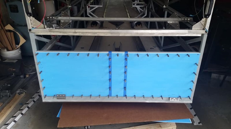
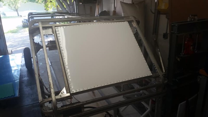
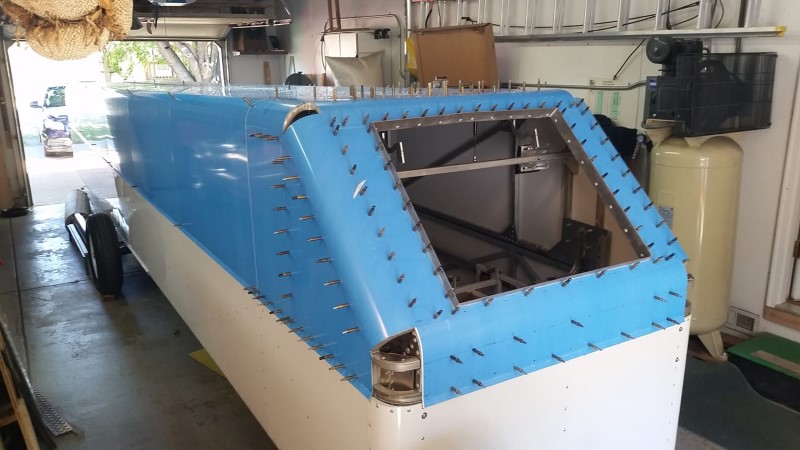
I started closing up the trailer by skinning the tailgate and back surface of the top, as these parts are all flat and relatively small and simple. I used pre-painted 0.032" aluminum sheet to skin the trailer, which I was able to obtain in 4x8 and 4x10' sheets from a local sign shop. This is the ONLY way I would ever attempt to skin a trailer. No painting! The blue color is the protective coating on both sides of the sheet. I left it on until the skins were riveted on. Here the tailgate skin is clecoed in place after drilling all of the mounting holes.
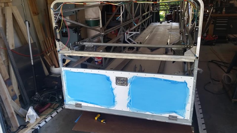
Here, the tailgate skin has been riveted on. Sealant was applied to both interfacing parts, and each rivet was also dipped in sealant before installation. I used a pneumatic rivet puller to install the rivets, as there are over 2500 rivets attaching the skins. No way was I going to intstall all of those with a hand squeezer.
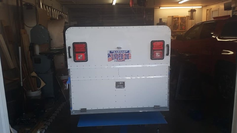
Here is the completed back end of the trailer, complete with lights, handles, and tag.
Next, I made the front hatch. It is basically just a frame of 3/4" aluminum angle riveted to some of the pre-painted sheet. I applied sealant between the mating parts and riveted it together with 1/8" protruding head solid rivets typically used in aircraft construction.
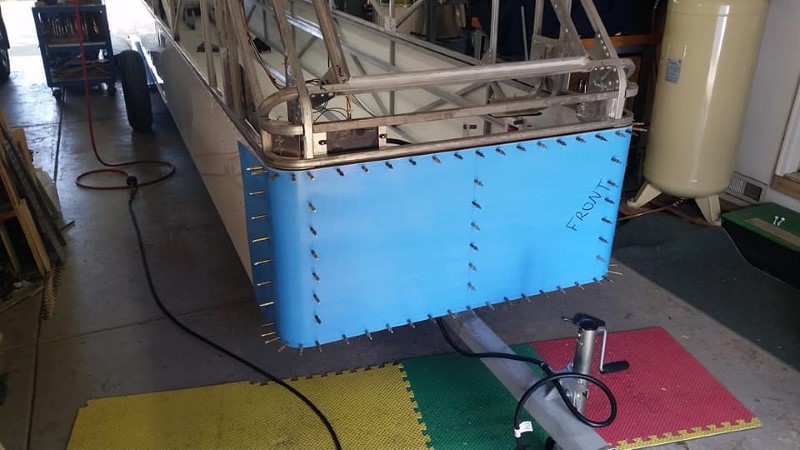
The bottom half of the trailer was skinned first, starting from back to front. Thankfully, around this time, my parents were in town for a week for the VSA Regatta held here in Wichita, and I took a week off of work and had my Dad help me fit and attach skins. It would have taken me another month to finish without his help.
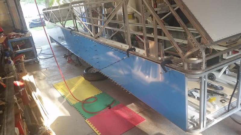
In one long day, we cut, drilled, attached, deburred, sealed, and riveted on all of the skins for the bottom half of the trailer.
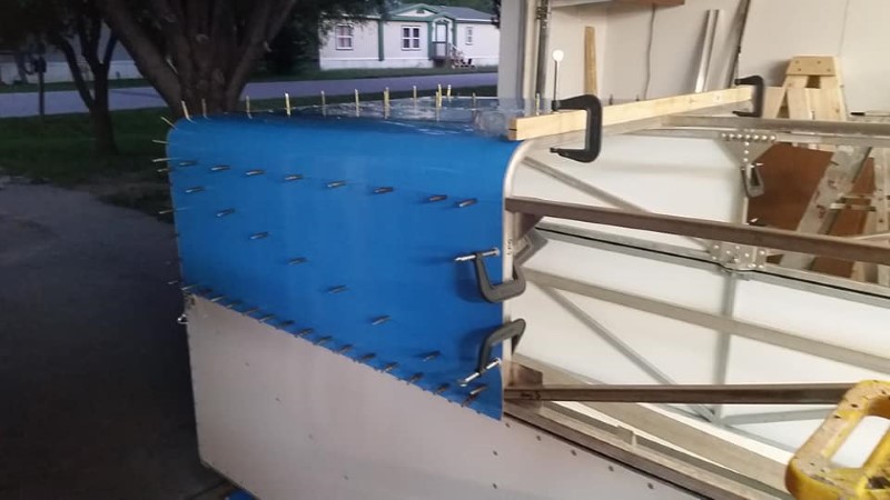
Here is the bending tool in use. Each skin for the majority of the top required two bends. This gadget made pretty quick work of it. Towards the end, we were down to about 30-40 minutes to fabricate, drill, and cleco a skin.
Similar to the lower half of the trailer, the clamshell top was skinned starting at the back so that water would run off and not be scooped in at the splices. I bought hundreds of clecos in the years prior to this project, knowing I would need a lot, and I still didn't have enough, as the larger skins required around 100 clecos to attach them while holes were being drilled.
I did not fly during the VSA regatta, as my Dad and I were busy fitting skins to the trailer instead. At this point, the front hatch has had the latch/hinge reinforcements installed, as well as the latches themselves. I found some replacement truck topper latches that worked perfectly, with one minor issue that I'll discuss later.
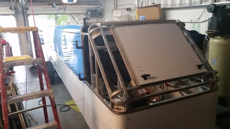
Here's a view with the hatch open as the skins around the front were being fitted.
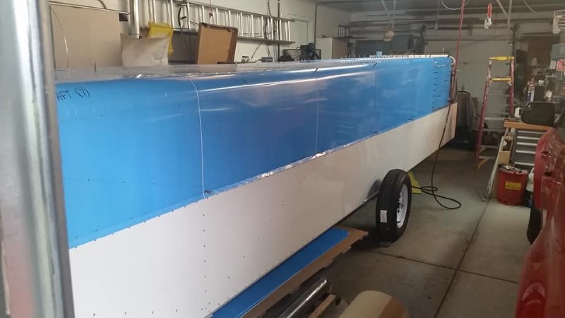
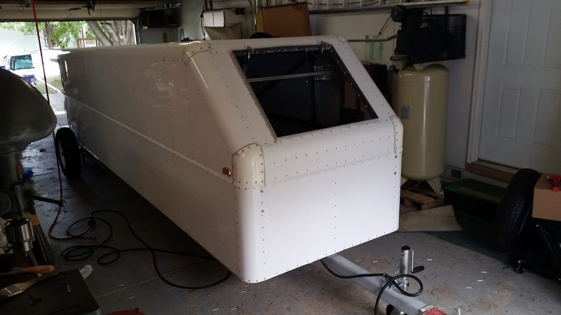
Finally, all of the skins are fitted!
Over the course of seven hours one Saturday, my neighbor and I sealed and riveted on all of the skins on the trailer top. Celebratory libations at the local bar followed, as the trailer was very close to completion at this point.
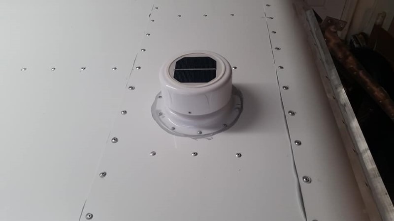
I installed two passive vents at the rear of the trailer, and this solar vent on top at the front. It keeps condensation from forming in cool weather and keeps the trailer at ambient temperature in hot weather.
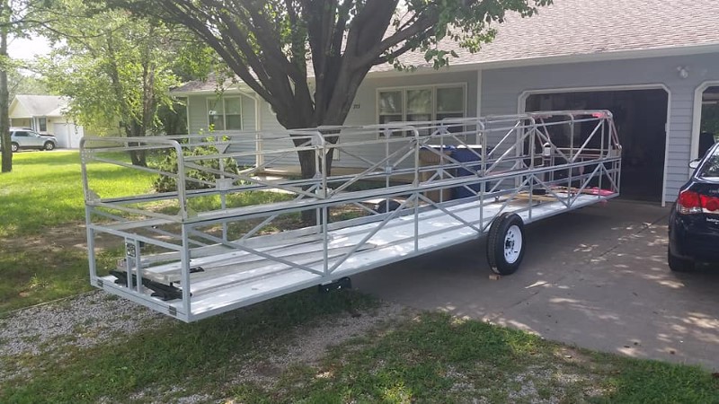
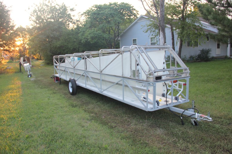
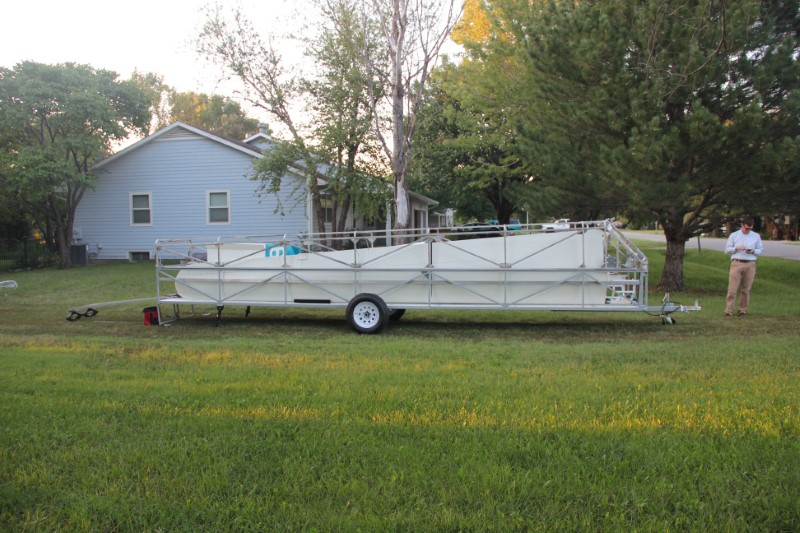
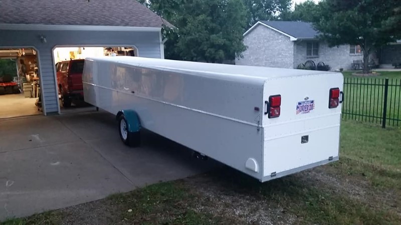
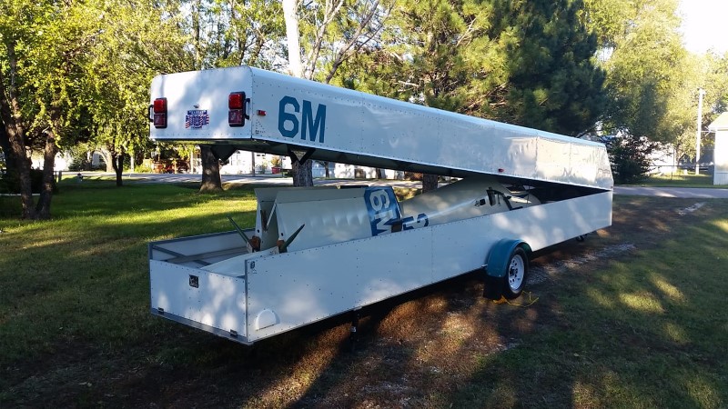
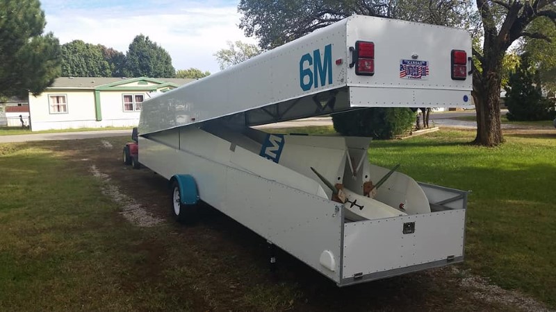
At this point, the trailer is functionally complete!
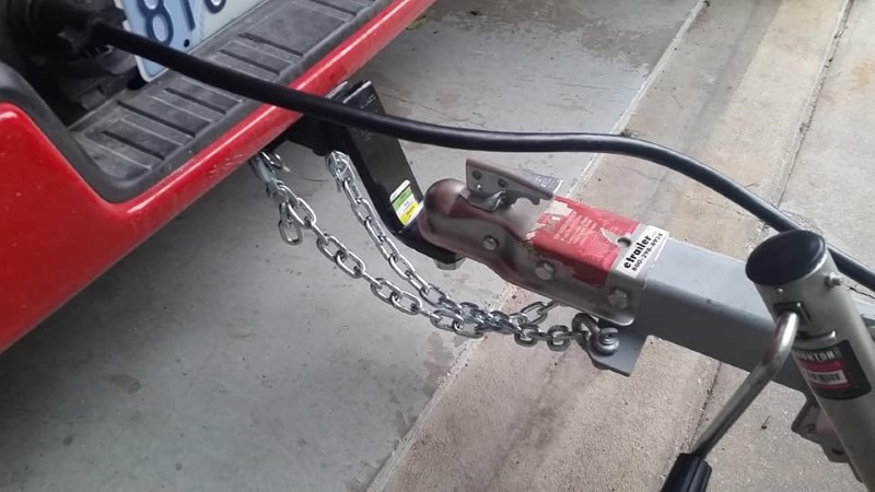
Safety chains were measured, cut and installed, and the wiring tested. I'm no sparky, but everything worked on the first try.
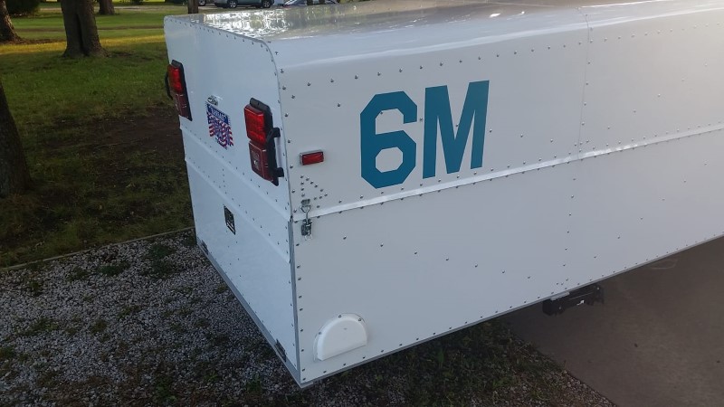
As a final touch, I bought some teal vinyl and cut and applied some contest numbers to match the SH1.
With the trailer now "done", some testing was required before permanently switching the glider to it. There would be no turning back, as the fuselage dolly would have to be permanently and irreversibly modified. All the bugs needed to be worked out first. The first test was a leak check since it conveniently rained a couple inches about a day after I finished the trailer. I rolled it outside for a couple hours, and then rolled it back in to look for leaks.
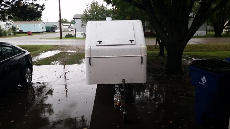
The good news: None of the skin joints, rivet holes, etc. leaked. The bad news: The front hatch leaked like a sieve. After studying where the water was ending up in the trailer, I isolated the leak to two different areas. First, water was overcoming the hatch seal at the top edge of the hatch, and the two locking latches were designed to be mounted to a vertical surface and not a slanted one, so in this application, they scooped water. I fixed the former by adding a chunk of bulb seal to the top edge of the hatch frame, as shown in this photo:
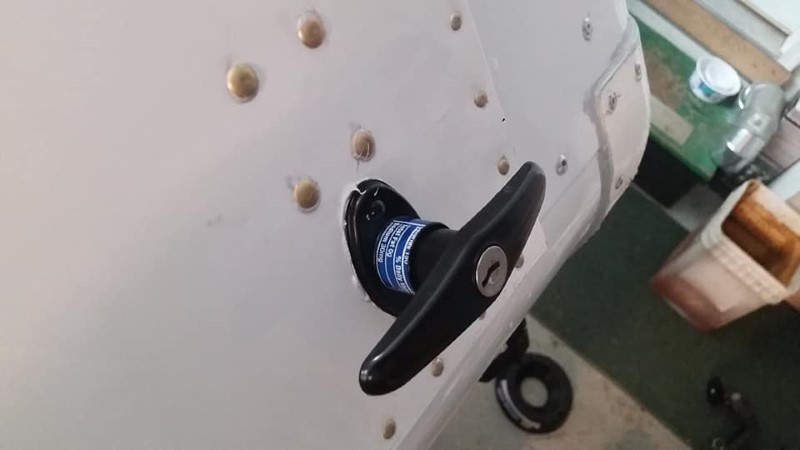
Sealing the latches required some thought. I ended up cutting a chunk out of a pop can, wrapping it around the body of the latch to form a sliding seal, and then wrapped that with self-adhesive silicone tape, and then attached it to the handle of the latch with a zip tie. This prevents water from coming in through the latches.
Finally, there was hardly anything left to do except to put the glider into the trailer for good.
It was great to FINALLY see the old trailer empty! (And T-shirt weather in mid October!)
One last small task with the glider in the trailer: interior lighting. I figured this would be handy in the event that I had a good long flight and the glider had to be disassembled in the dark. I bought a couple of LED bar lights and attached one to the rear of the trailer, and one to the front.
I wired the lights such that they could be powered by either the 12V aux wire coming from the vehicle, or with the glider's battery.
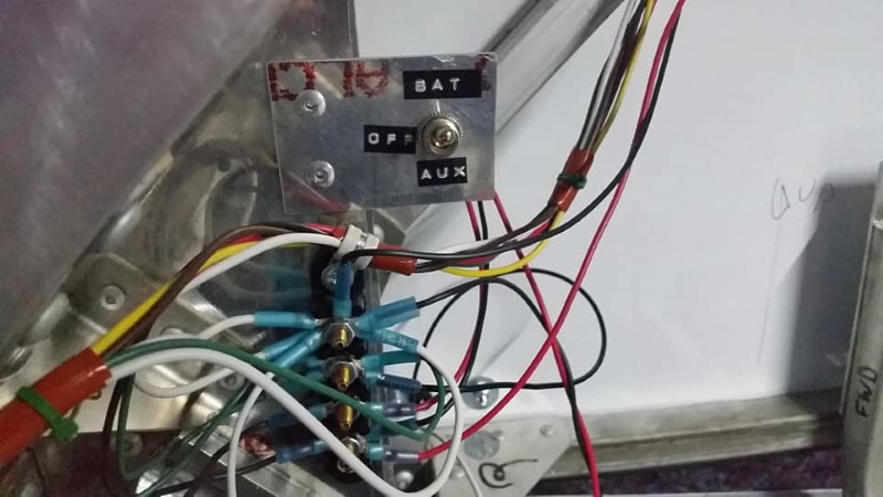
On what ended up being the last day of scheduled operations in our club, I made it up to the gliderport with the new trailer on October 28th. It took about 45 minutes to assemble the glider, as we were re-learning everything, but it went together fairly easy, and without back soreness afterwards.
I have now rigged and flown 6M out of the new trailer a few times. Each time gets easier and faster. I had relatively few issues. The first is that the fenders have to be remounted, as mounting them to the axle shook them to pieces in a hurry. Someday I'll mount them to the side of the trailer. I also had to make a small ramp for the main wheel on the glider to sit in when rigging the glider, as the jacks don't lower the ramp low enough to free the fuselage dolly without it. Otherwise, it has functioned almost flawlessly, and I'm looking forward to many years of use out of this trailer, hopefully without having to work on it all the time!
One thing I did learn: If I were to do this again, I'd probably build a tube trailer. It'd take about half as long as the clamshell, and probably cost less, too.
What follows here is a list containing more details of various items I used to build the trailer, in no particular order.
| Item | Description | Part Number | Source |
|---|---|---|---|
| Sealant | Everywhere I use the word "sealant" in this writeup, this is what I am referring to. It is compatible with all materials used in the trailer, paintable, and has a 24-hour cure time, which is useful for skins and other things that take awhile to fasten down. This was used to seal anything and everything. | Loc-Tite UR7001 | Grainger |
| Construction Adhesive | All of then interior gusseted, riveted joints on the clamshell top were glued in addition to riveted for better durability. This product is suitable for bonding various materials together, including metal to metal. I sanded the oxide layer off of the mating parts with a scotchbrite wheel, cleaned the residue off with isopropyl alcohol, and then sprayed the two halves of the joint with water in a spray bottle prior to assembling the joint. This helps the adhesive cure faster, according to the instructions. | Loc-Tite PL Premium | Home Center (Menards) |
| Paint - Trailer Frame | After extensive internet research, I determined this was the best coating I could use to paint the steel parts of the trailer. According to the manufacturer and various internet reviews, it is as good (or very nearly so) as hot-dip galvanizing when applied properly. I applied two coats with a brush. As of early 2020, it still looks like new after sitting outside for a year and a half. The only downside to this product is that it added around 20 lbs to the weight of the trailer. | ZRC Galvanizing Compound | GME Supply |
| Primer - Fiberglass Parts | This is the primer for the topcoat I selected below for the fiberglass parts of the trailer, including a portion of the underside of the floor panels, as well as the fiberglass corners on the clamshell top. It dries pretty quickly, can be rolled, brushed, or sprayed, and seems to have promoted good adhesion. | TotalBoat Topside Primer | Amazon |
| Paint - Fiberglass Parts | Topcoat for the fiberglass parts. I chose this because it is a single-part paint (no mixing of components) with good reviews. So far it is holding up well. My only complaint is that it is not brilliant white in comparison to the prepainted metal covering the trailer- it has a bit of a yellow cast to it. | TotalBoat Wet Edge One-Part Polyurethane Paint | Amazon |
| Machining Lubricant | I had heard good things about this machining lube, and have also seen it in use in aircraft production where I work. It is a bit spendy ($34 for a 12 oz tub), but I have found nothing better for drilling aluminum and stainless steel. It also works well on steel. It is a paste below about 75 degrees Farenheit. I keep it in my beer fridge to keep it solid during the summer. It is made from personal care products, so it won't hurt skin and does not make giant clouds of acrid smoke like other cutting oils I have used. I only used about half of this tub during the course of the trailer build. The rest of it will probably last me a decade of smaller projects. | Boelube 70302-12 | Amazon, The Yard Store |
| Trailer Tongue Jack | This is the current version of the trailer tongue jack that I used. A folding, wheeled jack is operationally ideal for a glider trailer. I am not a fan of fixed jacks and jacks without a wheel. This one is reasonably priced and even has a grease fitting for lubricating the mechanism inside. | Ironton 44062 | Northern Tool |
| Wiring Connector and Junction Box | I used this 8' 7-wire trailer plug and cord assembly. It came equipped with a junction box. The box and wires are well made. I don't think the box would seal perfectly for an exterior application, but it works great inside my trailer. | MIC-TWB-031 | Amazon |
| Wiring Supplies | A coworker turned me onto this internet supplier, Del City, for various electrical items for my trailer. I bought 100' rolls of 14 and 16 ga wire in various colors, as well as some terminal blocks. At the time, they had the best deal on large rolls of wire. | Various | Del City |
| Hatch Handles | I bought this pair of locking handles for the front hatch on the trailer. They are intended to be replacement handles for the back window of a truck topper shell. They are keyed alike and work great, other than the water leakage problem I encountered that was described above in the testing section. | Bauer T311-2 | Amazon |
| Tailgate Hinges | I used these blank stainless steel hinges for the tailgate, and drilled and countersunk holes in them. McMaster-Carr has a variety of hinges, both with and without holes. | 1624A68 | McMaster-Carr |
| Gas Springs | One of the design goals was to use as many off-the-shelf components as possible, as to avoid issues with extremely expensive replacement parts, i.e. $600 pairs of gas springs for a Cobra trailer. McMaster-Carr has a good selection of sizes and strengths. These two part numbers are for the hatch and clamshell, respectively. | 4138T538 4138T634 |
McMaster-Carr |
| Draw Latches | I used these draw latches as an additional means of holding the trailer top closed. These do most of the work, and the locking latch in the tailgate is basically a fail-safe. | 13435A320 | McMaster-Carr |
| Pull Handles | All four corners of the trailer have a plastic handle to aid in moving the trailer around when not connected to a vehicle. These have an appropriate load rating and are holding up well so far. | 5193A2 | McMaster-Carr |
| Rivets- Skin Attachment | Sealed blind rivets must be used to install the skins, or the trailer will leak. These are 3/16" in diameter and also have an aluminum mandrel. Aluminum rivets with a steel mandrel tend to have corrosion issues in my experience, so I used aluminum rivets with aluminum mandrels exclusively on this project. | 97524A034 | McMaster-Carr |
| Rivets - Interior Structure | I used these wide thickness range high-strength blind rivets on the interior of the trailer. I used both 3/16" and 1/4" rivets. The example part number here is for the 1/4" rivets. These rivets are very strong, and are in between hardware store cheap pop rivets and aerospace blind rivets in terms of cost. There are over $1000 in rivets in this trailer, representing about 15% of the total cost. | 98778A503 | McMaster-Carr |
| Stabilizer Jacks | These are the folding stabilizer jacks I used at the back of the trailer to prevent it from tipping when the glider is rigged. They are intended for an RV or camper trailer. These particular jacks are not available at the time of this writing, but the retailer has similar items. | TJ01RT-HD | eTrailer.com |
| Air Vents | I installed one solar and two passive vents in the trailer. This keeps the glider from getting cooked in the summer, and also prevents condensation in winter. | UF53-95001 (solar) WHMAV2-WAVT2 (passive) |
eTrailer.com |
| Clearance Lights | These are the amber, red and amber/red combo clearance lights I used on the trailer. All of these lights are LEDs. The length of the trailer necessitates front, rear, and middle clearance lights to comply with DOT regulations. Note that the mounting brackets for these lights are sold separately. | AL82AB (Amber) AL82RB (Red) MCL65ARB (Middle) |
eTrailer.com |
| Taillights | I used these recessed LED taillight/turn signal assemblies. They also contain an incandescent bulb for the reverse lights. | Bargman 3484008 | eTrailer.com |
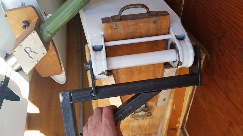
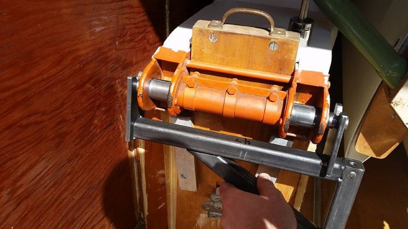
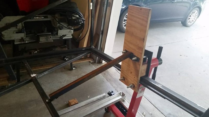
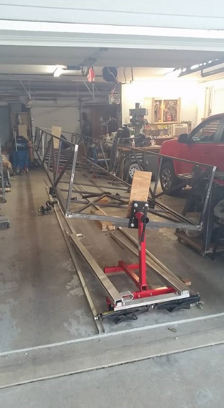
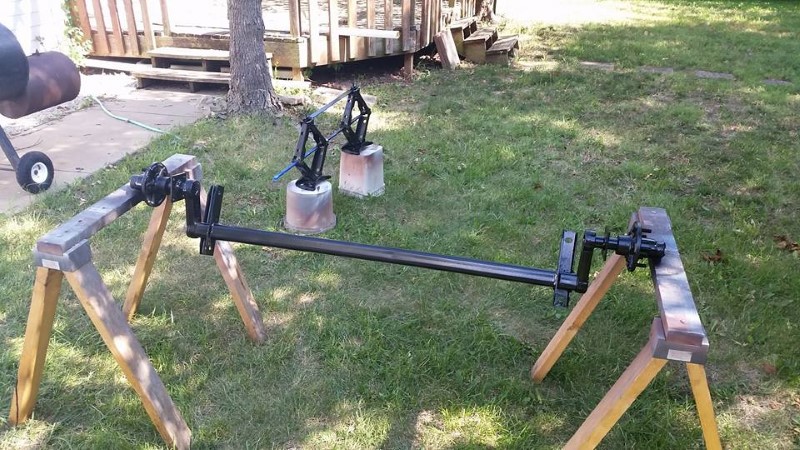
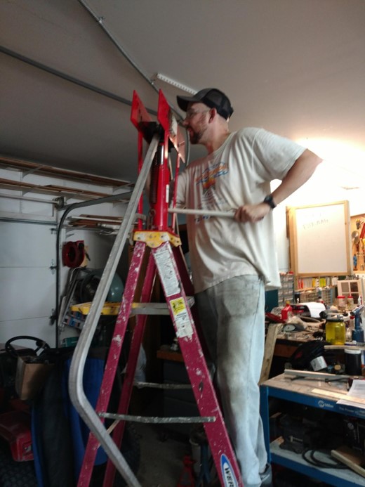
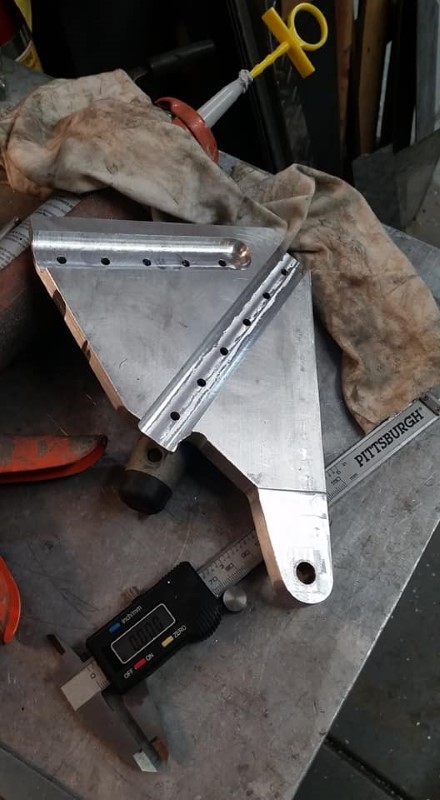
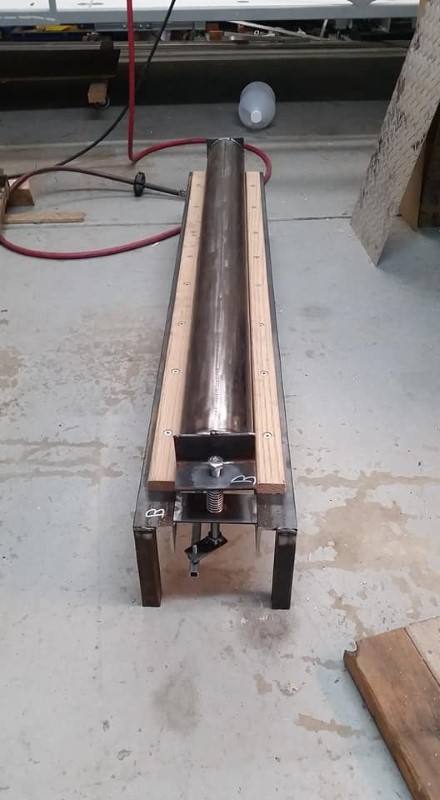
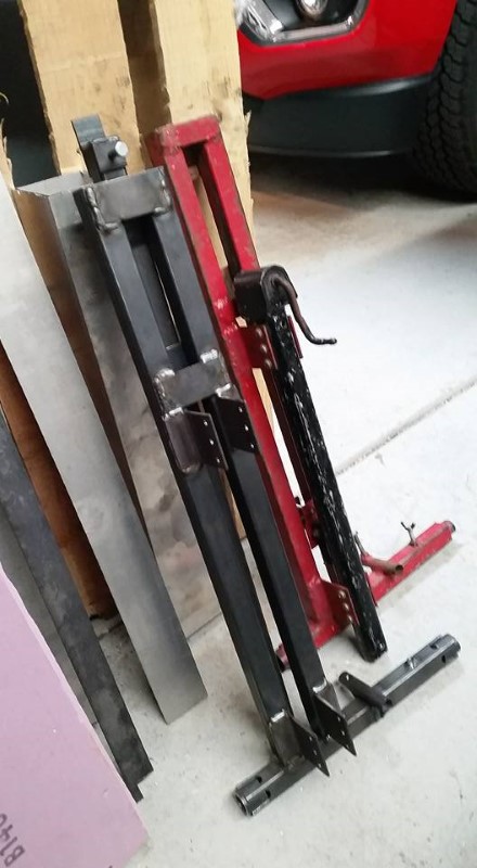
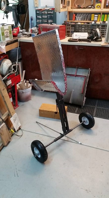
In addition to the trailer, I built a wing rigger to help me assemble the glider. The SH1 assembles easily, but the wings are around 165 lbs each, and are not fun to lift at the end of a 100-degree day after soaring for hours. No one makes a rigger for an old glider with thick wings (that I know of), so I made my own. Steve Leonard graciously let me borrow one of his that I particularly liked, and I took some time in the middle of the trailer build to copy it. It uses a slightly modified emergency jack from a 1998-2003 Mercedes W210, E320, CLK320, CLK430, and possibly several other models as the height adjustment. Most of the structure is 1" x 0.085" wall square tubing (with some 0.063" wall used here and there...I was basically using up leftovers from the trailer). The sliding axle is a piece of 3/4" steel rod with the ends turned down to 5/8" to accept the wheels.
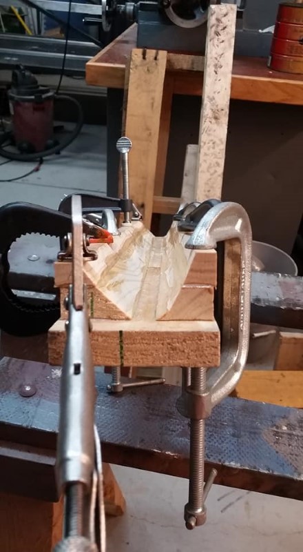
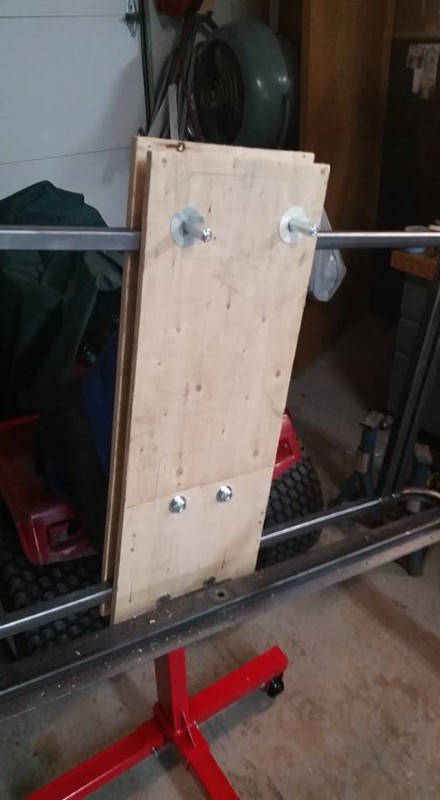
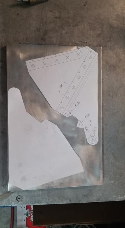
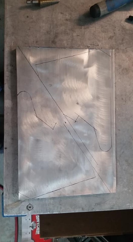
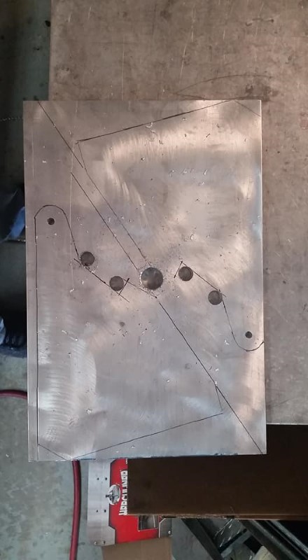
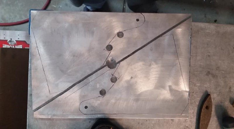
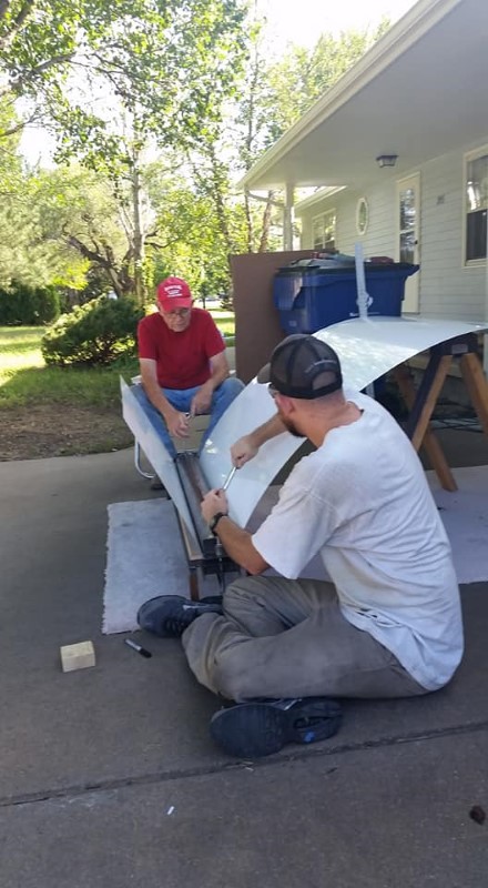
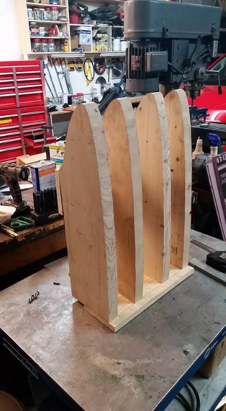
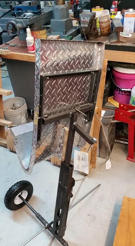
To make the wing cradle, I made a wooden form with the airfoil template at the appropriate wing station. (To determine this, I took the known approximate CG location of the wing given in the trailer interface drawing, and positioned the rigger for a ~20lb load in your hands at the root when maneuvering the wing.) I then wrapped some aluminum diamond plate around it and MIG welded (with a spool gun set up for aluminum) a rib all the way around the periphery to stiffen it. Here is the wooden form:
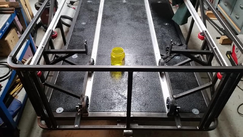
I then made a steel frame that has a variety of pivot points to connect the wing cradle to the base of the rigger. I wasn't sure where the pivot point should be along the chord, thus the reason for the series of holes. Not pictured is the trailing edge clamp that keeps the wing from falling out of the back of the rigger when it is being installed in the glider. I'll have to grab a picture of that next time I fly.
Well, that's it! Feel free to contact me with comments or questions, to report a broken link or egregious typo, etc. at matt.gonitzke@gmail.com.
All content and images Ⓒ 2020 Matt Gonitzke mgonitzke.net